What is the π-type RC and LC filter circuit identification method?
π-type RC filter circuit identification method
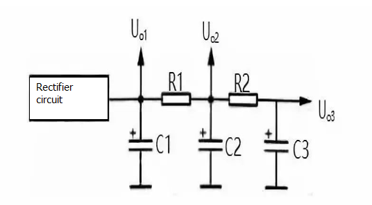
Figure 1 shows the π-type RC filter circuit. C1, C2 and C3 in the circuit are 3 filter capacitors, R1 and R2 are filter resistors, C1, R1 and C2 form the firstπ-type RC filter circuit, and C2, R2 and C3 form the secondπ-type RC filter circuit. Since this filter circuit is in the form of a Greek letter π and a resistor or capacitor, it is called aπ-type RC filter circuit.

Fig.1π-type RC filter circuit.
The principle of the π-type RC filter circuit is as follows:
(1) The filtering principle of this circuit is that the voltage output from the rectifier circuit is first filtered through C1, and most of the AC components are filtered out, and then added to the filter circuit composed of R1 and C2. The capacitive reactance of C2 and R1 constitute a voltage dividing circuit. Because the capacitive reactance of C2 is small, the partial voltage attenuation of the AC component is large, achieving the filtering purpose. For DC power, since C2 has a DC blocking function, the R1 and C2 voltage dividing circuits do not have a voltage division attenuation for DC, so that the DC voltage is output through R1.
(2) C1 is the first section of filter capacitor, increasing the capacity can improve the filtering effect. However, when C1 is too large, C1 is charged for a long time at startup. This charging current flows through the rectifier diode. When the charging current is too large and the time is too long, the rectifier diode will be damaged. Therefore, the use of this π-type RC filter circuit can make the C1 capacity smaller, and further improve the filtering effect by rationally designing the values of R1 and C2.
(3) When the size of R1 is constant, increasing the capacity of C2 can improve the filtering effect. When the capacity of C2 is constant, increasing the resistance of R1 can improve the filtering effect. However, the resistance of the filter resistor R1 should not be too large, because the DC current flowing through the load flows through R1, and a DC voltage drop occurs at R1, which reduces the DC output voltage Uo2. The greater the resistance of R1, or the greater the current flowing through the load, the greater the voltage drop across R1, making the DC output voltage lower.
(4) The magnitude of the three DC output voltages is different. Uo1 has the highest voltage. Generally, this voltage is directly applied to the power amplifier circuit or added to the circuit that requires the highest DC operating voltage and the largest operating current. The Uo2 voltage is slightly lower because the resistor R1 has a voltage drop to the DC voltage. Uo3 voltage At the lowest, this voltage is generally supplied to the front-end circuit as a DC operating voltage because the DC operating voltage of the pre-stage circuit is relatively low and the AC component in the DC operating voltage is required to be small.
(5) There are three DC voltage output terminals in this filter circuit, which output three sets of DC voltages Uo1, Uo2 and Uo3. Among them, Uo1 is only filtered through capacitor C1; Uo2 is filtered through C1, R1 and C2 circuits, so the filtering effect is better, the AC component in Uo2 is smaller; Uo3 is filtered through 2 filter circuits, the filtering effect is the best, so the communication component in Uo3 is the least.
π-type LC filter circuit identification method
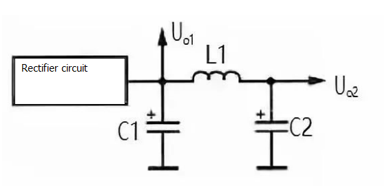
Figure 2 shows the π-type LC filter circuit. The π-type LC filter circuit is basically the same as the π-type RC filter circuit. This circuit only replaces the filter resistor with the filter inductor, because the filter resistor has the same resistance to the direct current and the alternating current, and the filter inductor has a large resistance to the alternating current inductor and a small resistance to the direct current, so that the filter effect can be improved without lowering DC output voltage.
In the circuit of Figure 2, the unidirectional pulsating DC voltage output by the rectifier circuit is first filtered through capacitor C1 to remove most of the AC components and then added to the L1 and C2 filter circuits.

Fig.1π-type LC filter circuit.
For the AC component, L1 is very sensitive to it, so that the AC voltage drop on L1 is large and the AC component added to the load is small.
For DC power, since L1 does not exhibit inductive reactance, it is equivalent to a conduction circuit. At the same time, the filter inductor uses a relatively large wire diameter and a small DC resistance. Therefore, there is substantially no voltage drop to the DC voltage, so the DC output voltage is relatively high, it is the main advantage of using an inductive filter.
If you want to know more, our website has product specifications for the filter, you can go to ALLICDATA ELECTRONICS LIMITED to get more information

