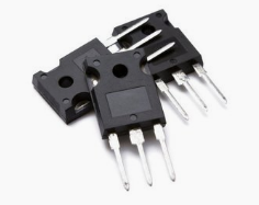
What is the principle and function of signal transmission by signal transistor?
The principle and function of signal transmission by signal transistor.
The three poles of the signal are used for the transmission of the signal. At the same time of signal transmission, it also plays the role of isolating the superior driving circuit from the inferior working circuit.
The transmission itself means that the transistor first receives the control signal from the superior driving circuit and then transmits it to the inferior working circuit through its own state change of "from cut-off to on" or "from on to cut-off". Therefore, the base pole of the transistor (inferior left pin) is often connected to the pin or BGA contact of the chip to receive the control signal from these chips. The collector or emitter is used as the input point or input line of the control signal in the inferior circuit.
The next question is how the transistor transmits the control signal from the base to the inferior working circuit through the collector and emitter.

Here, we emphasize once again that the three electrodes of the transistor are divided into the two different circuits mentioned above (superior driving circuit, inferior working circuit), and the base pole must belong to the superior driving circuit, while the collector and emitter have two specific cases (there is no essential difference between the two).
The first situation is as follows.
In the notebook computer motherboard, it is often found that such a NPN transistor, its emitter grounding, but also often found such a PNP transistor, its emitter connected to a certain pull-up power supply (the NPN transistor must be used to control the transmission of the signal, the above PNP transistor in the exclusion of power supply, almost certainly used to control the transmission of the signal).
The collector of such NPN transistor belongs to the inferior working circuit, and the emitter is grounding, so it can be considered that it does not belong to the superior driving circuit, nor does it belong to the inferior working circuit.
The collector of such PNP transistor belongs to the inferior working circuit, and the emitter is connected to a certain pull-up power supply, which can be considered as neither the superior driving circuit nor the inferior working circuit.
In order to understand the process of transmitting signal from transistor collector (NPN) or emitter (PNP), there must be an understanding conversion from "there is no current between EC before transistor conduction to there is current between EC after conduction" to "E pole or C pole level is' certain level 'before transistor conduction to' reverse phase level of E pole or C pole level 'after transistor conduction". In digital circuits, the current between PNP transistor EC or NPN transistor CE is not always important (it is of course very important). More importantly, the switching state between EC and CE will lead to the conversion of E pole or c pole level.
As mentioned earlier, the emitter of many NPN transistors on the motherboard is grounding, and the collector is pulled up to a high level by resistor. Once the NPN transistor responds to a high level on-control signal, the direct result is to turn on the collector and the emitter, and the indirect result will inferior the high level obtained by the collector through the pull-up resistance to the ground, and when the high-level conduction signal becomes low level, The collector of the NPN transistor will be restored from the ground level to the high level provided by the pull-up resistance.
In other words, the base of the NPN transistor can be output or high or low level on its collector under the control of the control signal, and the base of the PNP transistor can output or high or low level on its emitter under the control of the control signal. The high or low output level is the signal that is really transmitted to the inferior circuit by the transistor, and finally causes the change of the working state of the inferior working circuit.
The second scenario is as follows.
The collector and emitter of the transistor belong to the inferior working circuit.
In ATX power supply, the transistor used for the main switch is a typical case of this situation. This is because the collector and emitter of the main switch tube are actually in series in the loop, and the current from the collector to the emitter is the factor on which the circuit depends.
If you want to know more, our website has product specifications for signal transistor, you can go to ALLICDATA ELECTRONICS LIMITED to get more information

