| Allicdata Part #: | ADS131M08IPBS-ND |
| Manufacturer Part#: |
ADS131M08IPBS |
| Price: | $ 11.49 |
| Product Category: | Integrated Circuits (ICs) |
| Manufacturer: | Texas Instruments |
| Short Description: | 24-bit Analog-to-Digital Converter - ADC, 32-kSPS,... |
| More Detail: | N/A |
| DataSheet: |  ADS131M08IPBS Datasheet/PDF ADS131M08IPBS Datasheet/PDF |
| Quantity: | 1500 |
| 1 +: | $ 11.49000 |
| Series: | ADS131M08 |
| Packaging: | Tray |
| Part Status: | -- |
| Kit Type: | -- |
| Quantity: | 250 |
| Kit Contents: | -- |
| Mounting Type: | Surface Mount |
| Packages Included: | -- |
| Base Part Number: | ADS131M08 |
Due to market price fluctuations,if you need to purchase or consult the price.You can contact us or emial to us: sales@allicdata.com
1. Description
The ADS131M08IPBS is an eight-channel, simultaneouslysampling, 24-bit, delta-sigma (ΔΣ), analog-to-digital converter (ADC) that offers wide dynamic range, low power, and energy-measurement-specific features, making the device an excellent fit for energy metering, power metrology, and circuit breaker applications. The ADC inputs can be directly interfaced to a resistordivider network or a power transformer to measure voltage or to a current transformer or a Rogowski coil to measure current. The individual ADC channels can be independently configured depending on the sensor input. A lownoise, programmable gain amplifier (PGA) provides gains ranging from 1 to 128 to amplify low-level signals. Additionally, this device integrates channel-tochannel phase calibration and offset and gain calibration registers to help remove signal-chain errors. A low-drift, 1.2-V reference is integrated into the device reducing printed circuit board (PCB) area. Optional cyclic redundancy checks (CRCs) on the data input, data output, and register map maintain communication integrity. The complete analog front-end (AFE) is offered in a 32-pin TQFP package or a leadless 32-pin WQFN package and is specified over the industrial temperature range of –40°C to +125°C.
2. Features
1. 8 simultaneously sampling differential inputs
2. Programmable data rate up to 32 kSPS
3. Programmable gain up to 128
4. Noise performance:
– 102-dB dynamic range at gain = 1, 4 kSPS
– 80-dB dynamic range at gain = 64, 4 kSPS
5. Total harmonic distortion: –100 dB
6. High-impedance inputs for direct sensor connection:
– Input impedance 330-kΩ for gains of 1, 2, and 4
– Input impedance ≥ 1-MΩ for gains of 8, 16, 32, 64, and 128
7. Programmable channel-to-channel phase delay calibration:
– 244-ns resolution, 8.192-MHz fCLKIN
8. Current-detect mode allows for extremely low power tamper detection
9. Fast startup: first data within 0.5 ms of supply ramp
10. Integrated negative charge pump allows input signals below ground
11. Crosstalk between channels: –120 dB
12. Low-drift internal voltage reference
13. Cyclic redundancy check (CRC) on communications and register map
14. 2.7-V to 3.6-V analog and digital supplies
15. Low power consumption: 6.0 mW at 3-V AVDD and DVDD
16. Packages: 32-pin TQFP or 32-pin WQFN
17. Operating temperature range: –40°C to +125°C
3. Applications
1. Electricity meters: commercial and residential
2. Circuit breakers
3. Protection relays
4. Power quality meters
5. Battery test equipment
6. Battery management systems
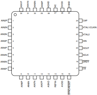
4. Pin configuration

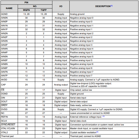
5. Pin Description

6. Clocking and Power Modes
The master clock can either be sourced externally to the CLKIN pin or generated internally using the onboard oscillator that requires a crystal connected between the XTAL1/CLKIN and XTAL2 pins. For optimal performance, the modulator sampling clock must be synchronous with the serial data clock (SCLK). The modulator sampling clock is derived from the master clock, which means the master clock must be synchronous with SCLK. Therefore, for best performance, supply a master clock to CLKIN and make sure data retrieval is synchronous to the clock signal at CLKIN. When not in use, turn the internal oscillator off to save power. The PWR[1:0] bits in the CLOCK register allow the device to be configured in one of three power modes: highresolution (HR) mode, low-power (LP) mode, and very low-power (VLP) mode. Changing the PWR[1:0] bits scales the internal bias currents to achieve the expected power levels. The external clock frequency must follow the guidance provided in the Recommended Operating Conditions table corresponding to the intended power mode in order for the device to perform according to the specification.
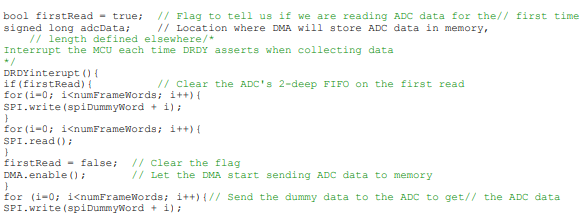
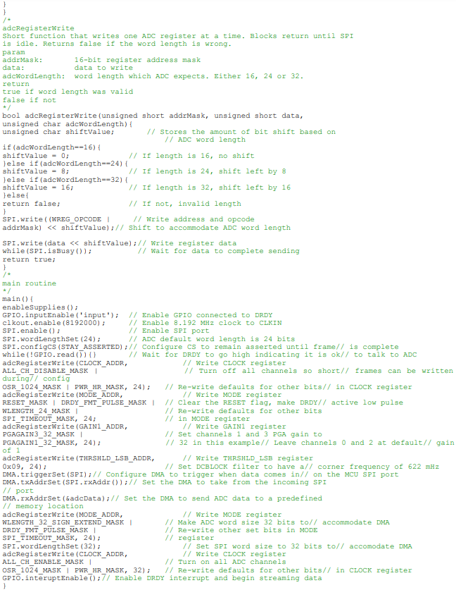
7. Code Example
This section contains example pseudocode for a simple program that configures and streams data from the ADS131M08. The pseudocode is written to resemble C code. The code uses several descriptive precompilerdefined constants that are indicated in upper case. The definitions are not included for brevity. The program works in three sections: MCU initialization, ADC configuration, and data streaming. This code is not optimized for using the fast startup feature of the ADS131M08. The MCU is initialized by enabling the necessary peripherals for this example. These peripherals include an SPI port, a GPIO configured as an input for the ADS131M08 DRDY output, a clock output to connect to the ADS131M08 CLKIN input, and a direct memory access (DMA) module that streams data from the SPI port into memory without significant processor intervention. The SPI port is configured to a 24-bit word size because the ADC default SPI word size is 24 bits. The CS pin is configured to remain low as long as the SPI port is busy so that it does not de-assert in the middle of a frame. The ADC is configured through register writes. A function referred to as adcRegisterWrite writes an ADC register using the SPI peripheral. No CRC data integrity is used in this example for simplicity, but is recommended. The ADC outputs are initially disablo short frames can be written during initialization consistent with the guidance provided in the Short SPI Frames section. The ADC is configured to output DRDY as pulses, the gain is changed to 32 for channels 1 and 3, and the DC block filter is used with a corner frequency of 622 mHz. Finally, the ADC word size is changed to 32 bits with an MSB sign extension to accommodate the MCU memory length and to allow for 32-bit DMA transfers. All other settings are left as defaults. Data streaming is performed by using an interrupt that is configured to trigger on a negative edge received on the GPIO connected to the DRDY pin. The interrupt service routine, referred to as DRDYinterrupt, sends six 32- bit dummy words to assert CS and to toggle SCLK for the length of the entire ADC output frame. The ADC output frame consists of one 32-bit status word, four 32-bit ADC conversion data words, and an optional 32-bit CRC word. The frame is long enough for output CRC even though the CRC word is disabled in this example. The DMA module is configured to trigger upon receiving data on the SPI input. The DMA automatically sends the ADC data to a predetermined memory location as soon as the data are shifted into the MCU through the SPI input.


| Part Number | Manufacturer | Price | Quantity | Description |
|---|
| ADS1131IDR | Texas Instru... | -- | 1000 | IC ADC 18BIT SRL 10/80SPS... |
| ADS1286UC | Texas Instru... | 5.08 $ | 125 | IC 12BIT 20K UNIPOL A/D 8... |
| ADS114S08BIPBSR | Texas Instru... | -- | 1000 | 16BIT ADC16 Bit Analog to... |
| ADS1213U/1K | Texas Instru... | 10.05 $ | 1000 | IC 22BIT DELTA-SIGMA ADC ... |
| ADS1286P | Texas Instru... | -- | 1000 | IC 12-BIT SAMPLING A/D 8-... |
| ADS1220IRVAR | Texas Instru... | 32.83 $ | 7999 | IC ADC 24-BIT 2KSPS 16-VQ... |
| ADS1213U | Texas Instru... | -- | 2410 | IC 22-BIT DELTA-SIGMA A/D... |
| ADS1208IPWR | Texas Instru... | 0.0 $ | 1000 | IC MODULATOR DELTA-SIGMA ... |
| ADS1100A0IDBVRG4 | Texas Instru... | 1.62 $ | 1000 | IC ADC 16-BIT I2C PROGBL ... |
| ADS1251U/2K5G4 | Texas Instru... | 4.68 $ | 1000 | IC ADC CONV 24BIT LP 8-SO... |
| ADS1220EVM | Texas Instru... | 71.96 $ | 19 | MODULE EVALUATION FOR ADS... |
| ADS1252EVM | Texas Instru... | 0.0 $ | 1000 | EVAL MOD FOR ADS1252ADS12... |
| ADS1672EVM | Texas Instru... | 0.0 $ | 1000 | EVAL MODULE FOR ADS1672AD... |
| ADS1112IDGST | Texas Instru... | -- | 4750 | IC ADC 16-BIT I2C PROGBL ... |
| ADS1245IDGST | Texas Instru... | -- | 1000 | IC ADC LP 24-BIT 10-MSOP2... |
| ADS131E08SPAG | Texas Instru... | 11.0 $ | 1000 | IC AFE 24BIT 64KSPS 64TQF... |
| ADS1601IPFBTG4 | Texas Instru... | 8.73 $ | 1000 | IC ADC 16BIT 1.25MSPS 48-... |
| ADS1625IPAPRG4 | Texas Instru... | 0.0 $ | 1000 | IC 18BIT 1.25MSPS ADC 64-... |
| ADS1242IPWRG4 | Texas Instru... | 3.58 $ | 1000 | IC ADC 24-BIT SER PROGBL ... |
| ADS1216Y/250G4 | Texas Instru... | 8.93 $ | 1000 | IC ADC CONV 24BIT DEL/SIG... |
| ADS1210U/1KG4 | Texas Instru... | -- | 1000 | IC 24BIT DELTA-SIGMA ADC ... |
| ADS1245IDGSRG4 | Texas Instru... | 0.0 $ | 1000 | IC ADC LP CONVERT 24BIT 1... |
| ADS130E08IPAGR | Texas Instru... | -- | 1000 | IC AFE 16BIT 8CH 8KSPS 64... |
| ADS131E08SPAGR | Texas Instru... | -- | 1000 | IC AFE 16/24BIT 64KSPS 64... |
| ADS1205IRGERG4 | Texas Instru... | 3.93 $ | 1000 | IC MODULATOR DELTA-SIGMA ... |
| ADS1110A0IDBVRG4 | Texas Instru... | 1.9 $ | 1000 | IC ADC 16-BIT I2C PROGBL ... |
| ADS1224IPWTG4 | Texas Instru... | 4.35 $ | 1000 | IC 24BIT AD CONVERTER 20-... |
| ADS1230REF | Texas Instru... | 0.0 $ | 1000 | ADS1230REFADS1230 - 20 Bi... |
| ADS1281EVM-PDK | Texas Instru... | 108.3 $ | 1 | KIT PERFORMANCE DEV FOR A... |
| ADS1602IPFBT | Texas Instru... | 9.3 $ | 1000 | IC ADC 16BIT 2.5MSPS 48-T... |
| ADS1601IPFBR | Texas Instru... | 6.55 $ | 1000 | IC ADC 16BIT 1.25MSPS 48-... |
| ADS1110A0IDBVTG4 | Texas Instru... | 3.04 $ | 1000 | IC ADC 16-BIT I2C PROGBL ... |
| ADS1672IPAGRG4 | Texas Instru... | 10.03 $ | 1000 | IC ADC 24-BIT 78.1K-625K ... |
| ADS1211P | Texas Instru... | -- | 1000 | IC 24-BIT DELTA-SIGMA A/D... |
| ADS1204IRHBT | Texas Instru... | -- | 250 | IC MODULATOR DELTA-SIGMA ... |
| ADS1271EVM | Texas Instru... | 35.62 $ | 5 | EVALUATION MODULE FOR ADS... |
| ADS1241E/1K | Texas Instru... | -- | 1000 | IC ADC 24-BIT SER PROGBL ... |
| ADS1110A1IDBVR | Texas Instru... | -- | 1000 | IC ADC 16-BIT I2C PROGBL ... |
| ADS1610IPAPR | Texas Instru... | 18.49 $ | 1000 | IC ADC 16BIT 10MSPS 64-HT... |
| ADS1211PG4 | Texas Instru... | 0.0 $ | 1000 | IC 24BIT DELTA-SIGMA ADC ... |
24-bit Analog-to-Digital Converter - ADC...

IC ADCBit Analog to Digital Converter I...

IC ADCBit Analog to Digital Converter I...

IC ADC 12BIT 4GSPS 68VQFN12 Bit Analog t...

IC ADC 16BIT CMOS 5V 48LFCSP16 Bit Analo...

IC ADC 14BIT 160MSPS 48VQFN14 Bit Analog...


