What is capacitance?

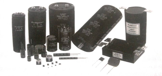
The publicity map of the Rubycon (Ruby) website is shown in figure 1.
Figure 1 publicity map of Rubycon (ruby) official website.
There are many types of capacitors, but they are classified by material and use.
"Electrolytic", "solid", "ceramic", "tantalum" and "polypropylene film" (CBB) are all materials (conductors or insulators) that describe the manufacture of capacitors.
"filtering", "coupling", "energy storage" bootstrap "," boost "partial voltage", "acceleration" and "delay" all describe the role of specific capacitors in the circuit.
The following is explained in turn.
(1) "filtering". Whether it is a computer motherboard belonging to digital circuits or other circuits belonging to analog circuits, in addition to transmitting the signals we need, it is inevitable that there is a "signal" that we do not need. It is more scientific to call this "signal" interference "or" noise ".
In power supply and signal, most of the interference is high frequency clutters, but there are also low frequency clutters (such as the 153resistor in the USB interface circuit of the desktop computer motherboard is used to filter the low frequency clutters to the ground). Therefore, we need to design a functional circuit in the circuit to separate the two, to leave what we need, to boot out of the circuit (which is the ground) or to consume it. Because capacitors have the function of "high frequency" resistance "low frequency", 0.01 ~ 1 μ F capacitors are commonly used to bypass to the ground, so that the high frequency interference in the circuit can be introduced into the ground and play the role of filtering out the interference.
(2) "Coupling". This is a typical application of capacitors for signal transmission. Coupling is generally used for the voltage of the transmitter and receiver of the signal. On the desktop computer motherboard, the most typical application is the coupling of audio signal transmission in the circuit around the sound card and the coupling of SATA interface circuit, and the inter-bridge bus and clock signal are also used.
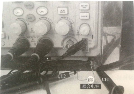
Fig. 2 shows a signal coupling demonstration circuit composed of a standard frequency source with an oscilloscope. The 1kHz square wave frequency source is connected to one end of the capacitance, the probe is connected to both ends of the capacitance, and the ground pass wire of the probe is connected to the 1kHz square wave frequency source.
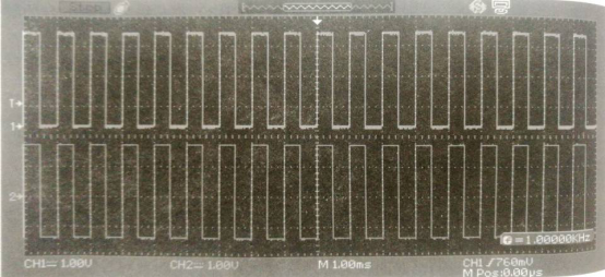
Figure 3 shows the measured waveform of the demonstration circuit.

As can be seen from the waveform of the CH2, it is basically a copy of the CH1. This shows that after the signal is input from one end of the coupling capacitance, it can be transmitted to the other end of the coupling capacitance in the form of a copy, which can be used by the lower circuit.
(3) "Energy storage". When the capacitance is charged, the electric energy is stored in the capacitance in the form of electric field.
(4) "bootstrap", "boost pressure". In any case where the N channel is driven on, it involves "bootstrap" and "boost". In most cases of driving N communication field tube to obtain a certain power supply, it often involves the "bootstrap" and "boost" of capacitance. However, in ATX power supply, these functions are integrated into the chip, readers do not need to care.

(5)"partial pressure". Here is the partial voltage of the capacitor in series. Readers are familiar with the series partial voltage of resistance. It is very similar to the series partial voltage of resistance.
(6)"accelerate". If there's no resistance, it transmits a signal. If we use a capacitance in parallel with this resistor, it is tantamount to adding a branch to the signal. The only function of this capacitance is to reduce the time of the signal from the input to the output of the resistor, of course, the capacity of the capacitor is specially selected. Its electrical principle is that "current is ahead of voltage".
(7)"delay". Capacitance, as an energy storage element, is realized by charging capacitors by power supply. When the capacitance is charged with a constant voltage and a constant current, the voltage of one pin connected to the positive pole of the power supply will gradually increase from 0V (starting charging) to the voltage of the positive pole of the power supply (the end of charging), as shown in figure 4.

In the process, from "charging start" to "charging end" power supply is positive. The time required by the station is called the "charging time" of the capacitance. For the capacitance determined by the capacity, the charging time can be calculated accurately by the formula.
When the capacitance C is charged with a constant relatively small current I, the voltage of the capacitance C positive electrode increases until the voltage of the power supply positive pole is equal to that of the power supply positive pole after the charging is completed. To be more progressive, if we can select a controllable and constant charging current and a capacitance with a suitable capacity, then it is possible to accurately control the charging time so that the positive pole of the capacitance can reach the definite voltage value we expect after a certain length of time. This is the basis of capacitance for delay (delay).
In fact, most of the soft start feet of switching power supply chips are realized by charging their external capacitors with microampere current. In addition, the delay of PG signal of ordinary ATX power supply is also realized by capacitance charging.
If you want to know more, our website has product specifications for capacitance, you can go to ALLICDATA ELECTRONICS LIMITED to get more information

