HDMI interface circuit analysis and fault maintenance.
1. HDMI interface introduction.
High Definition Multimedia Interface, HDMI is a kind of digital video and audio interface technology. It is a special digital interface suitable for video transmission. It can transmit audio and audio signals simultaneously. The highest data transmission speed is 5Gbps. At the same time, there is no need for digital / analog or analog / digital conversion before the signal is transmitted. HDMI supports EDID,DDC2B, so HDMI devices have the feature of "plug and play" and "negotiation" automatically takes place between the signal source and the display device. Automatic selection of the most appropriate video, audio format.
2. The working principle of HDMI interface.
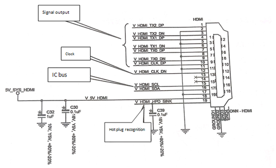
The HDMI interface circuit is shown in figure 1. V _ HDMI_TX_DP and VHDMI _ TX_ DN are the display image signal transmission lines, and V_HDMI_TX_DP and VHDMI _ TX_ DN are the clock signal lines of the interface. V_HDMI_SCL and VHDMI _ SDA are the IC bus of the interface, and V_HDMI_HPD_SINK is the hot swappable identification signal of the interface.

Fig. 1 HDMI interface circuit diagram.
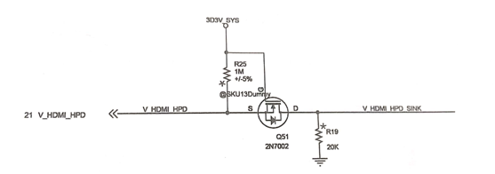
When the main board is connected to the monitor through the HDMI interface, the monitor sends out a V_HDMI_HPD_SINK signal to the HDMI port of the main board through the 19 pins of the HDMI interface, and then converts the V_HDMI_HPD signal to the North Bridge chip through the circuit shown in figure 2. The North Bridge chip reads the relevant parameters of the display through the IC bus of the HDMI interface. After reading the display parameters, the North Bridge chip outputs the video signal to the display through the HDMI display interface.

Fig. 2 HDMI interface identification signal circuit.
3. HDMI interface does not show the failure of the maintenance method.
1) Visually inspect the interface for damage.
2) Measuring if the V_HDMI_HPD_SINK voltage of the hot swappable signal is 5V.
3) Measure VHDMI / SVL of IC bus and whether VHDMI / SDA is normal.
4) Measure whether the data line HDMI_TX_DP,HDMI_TX_DN is short-circuited or open to the ground.
5) If the above is normal and does not appear, replace the HDMI connector.
6) Replacement interface has not been displayed, the final welding or replacement of the North Bridge chip.
This article is from Allicdata Electronics Limited. Reprinted need to indicate the source.

