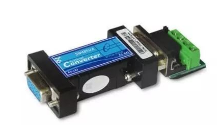
What are the RS-422 and RS-485 interfaces and what are their characteristics?
The half-duplex network composed of RS485 interface is generally a two-wire system, and shielded twisted pair transmission is mostly used. This wiring method is a bus topology. Up to 32 nodes can be connected on the same bus. We know that initially the data is a simple process of analog signal output, and later the instrument interface is an RS232 interface. This interface can implement point-to-point communication, but this method cannot realize the networking function, and the subsequent RS485 solves this problem. To this end, this article introduces the RS485 interface in detail in the form of question and answer.
1. What is the RS-485 interface? What are its characteristics compared with RS-232-C interface?
Answer: Since the RS-232-C interface standard appeared earlier, it is inevitable that there are deficiencies, mainly including the following four points:
(1) The signal level value of the interface is high, which is easy to damage the chip of the interface circuit, and because it is incompatible with the TTL level, it is necessary to use a level conversion circuit to connect with the TTL circuit.
(2) The transmission rate is low. In asynchronous transmission, the baud rate is 20Kbps.
(3) The interface uses a signal line and a signal return line to form a common ground transmission form. This common ground transmission is prone to common mode interference, so the anti-noise interference is weak.
(4) The transmission distance is limited. The standard value of the maximum transmission distance is 50 feet. In fact, it can only be used around 50 meters. In response to the shortcomings of RS-232-C, some new interface standards have emerged continuously. RS-485 is one of them. It has the following characteristics:
1) Electrical characteristics of RS-485: logic "1" is represented by the voltage difference between the two wires as +(2-6)V; logic "0" is represented by the voltage difference between the two wires as -(2-6)V . The interface signal level is lower than that of RS-232-C, it is not easy to damage the chip of the interface circuit, and the level is compatible with the TTL level, which can be easily connected with the TTL circuit.
2) The maximum data transmission rate of RS-485 is 10Mbps
3) The RS-485 interface is a combination of a balanced driver and a differential receiver, which enhances the ability to resist common mode interference, that is, has good resistance to noise interference.
4) The standard value of the maximum transmission distance of the RS-485 interface is 4000 feet, which can actually reach 3000 meters. In addition, the RS-232-C interface allows only one transceiver to be connected on the bus, that is, single station capability. The RS-485 interface allows up to 128 transceivers to be connected on the bus. That is, it has multi-station capability, so that users can easily establish a device network using a single RS-485 interface.
5) Because the RS-485 interface has good anti-noise interference, long transmission distance and multi-station capability, the above advantages make it the preferred serial interface. Because the half-duplex network composed of the RS485 interface generally only needs two wires, the RS485 interfaces are all shielded twisted pair transmission. The RS485 interface connector uses a DB-9 9-pin plug socket, the RS485 interface to the smart terminal uses DB-9 (hole), and the keyboard interface RS485 to the keyboard uses DB-9 (pin).
3. Points for attention in the network installation of RS-422 and RS-485
RS-422 can support 10 nodes, and RS-485 supports 32 nodes, so multiple nodes form a network. The network topology generally adopts a bus-type structure with terminal matching, and does not support ring or star networks. When constructing the network, the following points should be noted:

1. Use a twisted-pair cable as the bus to connect the nodes in series. The length of the lead from the bus to each node should be as short as possible to minimize the impact of the reflected signal in the lead on the bus signal. Shown are some common wrong connection methods (a, c, e) and correct connection methods (b, d, f) in practical applications. Although the three network connections a, c, and e are incorrect, they may still work normally at short distances and low rates. However, as the communication distance increases or the communication rate increases, the adverse effects will become more and more serious, mainly because The signal is superimposed on the original signal after being reflected at the end of each branch, which will cause the signal quality to deteriorate.
2. Pay attention to the continuity of the characteristic impedance of the bus, and signal reflection will occur at the point where the impedance is not continuous. The following situations are prone to this kind of discontinuity: different sections of the bus use different cables, or there are too many transceivers installed on a certain section of the bus close to each other, and the long branch line leads to the bus.
In short, a single, continuous signal channel should be provided as a bus.
If you want to know more, our website has product specifications for interfaces, you can go to ALLICDATA ELECTRONICS LIMITED to get more information

