What is transistor?
Transistor is a kind of signal transmission or voltage modulation element which widely exists in almost all circuit boards.
Transistor is a kind of signal transmission or voltage modulation element which widely exists in almost all circuit boards.


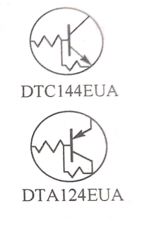
Symbol of the transistor Built-in resistance type
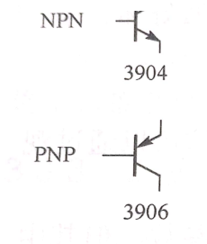
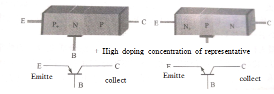
The structure and symbol of the transistor.
The transistor is a sandwich in structure: two layers of N-type semiconductors are sandwiched with a layer of P-type semiconductors to form NPN transistors, and two layers of P-type semiconductors are sandwiched with one layer of N-type semiconductors to form PNP transistors. Only when measured with a multimeter can the transistor be regarded as a simple combination of two diode. N-type semiconductors are also called multi-electron semiconductors: P-type semiconductors are also called electron-deficient semiconductors. They are all obtained by doping different hetero atoms into pure semiconductor materials. The doping concentration of the double N layer or the double P layer of the transistor is different, which determines the unidirectional current between the emitter and the collector of the transistor.
As shown in figure 1, the structure diagram of the NPN and PNP transistors and the symbols in the circuit are shown.

Current direction and working state between transistor EC.
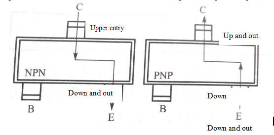
The current between the transistor collector and the emitter is unidirectional. When the NPN transistor is in the state of amplification and saturation, the current between EC ranges from C pole to E pole. When the PNP transistor is in the state of amplification and saturation, the current between EC ranges from E pole to C pole.

The current pattern between transistor CE is shown in fig. 1. It is especially emphasized that the base current also flows through in the amplification and saturation state, but the direction of the base current is not shown in the diagram. Here, the author agrees with the reader on the pin position of the tripod in the diagram. The base pin in the diagram is called "left lower pin", the collector pin in the diagram is called "middle pin", and the emission pole pin in the diagram is called "right lower pin".
Any transistor has only three working states: cut-off, amplification and saturation.
The so-called cutoff refers to the infinity of resistance between transistor CE. For the NPN transistor, the current cannot flow from the C pole to the E pole: for the PNP transistor, the current cannot flow from the E pole to the C pole. This is because the base of the transistor does not make the transistor turn on the appropriate voltage.
The so-called amplification refers to the fact that the resistance between transistor CE has been reduced from infinity to a constant current. This is because the base of the transistor has been appended with an appropriate voltage to turn on the transistor. For NPN transistor, the current will flow from c pole to E pole, and the base of NPN transistor will be attached to the positive conduction voltage. For the PNP three-stage tube, the current will flow from the E pole to the C pole, and the base will be extremely attached to the negative conduction voltage.
At any time, the Le=Lb + Lc of the NPN transistor and the Ic=1b+Ie. of the Ic=Ib* β, PNP transistor And Ic=lbx β, β is called magnification factor. That is to say, when the transistor is in the amplification working area, the emitter current of NPN collector and PNP is T times of that of the base current. This feature is used to control high current with small current (because there is a relatively strict multiple relationship between NPN base and emitter or PNP base and collector current).
Saturation refers to the fact that the resistance between transistor CE has been reduced to a minimum resistance of close to 0 Ω. This means that the positive conduction voltage attached to the NPN base electrode can completely turn on the transistor, and for the NPN transistor, the negative conduction voltage attached to the base electrode also makes the transistor fully conduction.
In this book, the concept of "internal consistency" of voltage at all levels of transistor in normal operation is put forward. That is, if the base voltage of NPN transistor is low and the collector voltage and emitter voltage can be different, the base voltage of PNP transistor is high and the collector voltage and emitter voltage can be different. If the transistor is in a saturated conduction state, the base voltage of NPN transistor should be high and the collector and emitter voltage should be the same. The base voltage of PNP transistor is low and the collector and emitter voltage should be the same. By using the "internal consistency" of the transistor, the preliminary blind test of the transistor in the work can be carried out.
If you want to know more, our website has product specifications for transistor, you can go to ALLICDATA ELECTRONICS LIMITED to get more information

