How to realize the asynchronous signal edge detection circuit?
The so-called edge detection (also called edge extraction) is to detect the rising and falling edges of the input signal. When designing a digital system, edge detection is a very important idea. The most commonly used sequential circuits in actual programming should be edge detection circuits and frequency dividers.
So, how to realize the edge detection circuit?
We know that posedge and negedge can be used directly to extract the rising and falling edges in the sensitive signal list of the always block, but what if you want to detect the rising or falling edge inside the always block? Still use poesedge and negedge? Obviously it is not possible, because such statements cannot be synthesized. I tried it in QuartusII. When compiling, it prompts "multiple event control statements not supported for synthesis!", which means it cannot be synthesized. In fact, posedge and negedge can only be used in the sensitive signal list of the always block or in the testbench, so let's do it in other ways.
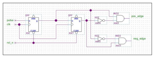
To realize edge detection, the most direct idea is to use two-level registers. The second-level register latches the input level when a certain clock rising edge arrives, and the first-level register latches the input voltage when the next clock edge arrives. If the level signals latched by these two registers are different, it means that an edge is detected. The specific rising edge or falling edge can be realized by combinational logic. As shown below:

Figure 1 Edge detection with two-level registers
The above figure is represented by a block diagram, or it can be written in verilog, the code is as follows:
When a rising edge is detected, the pos_edge signal outputs a high level for one clock cycle; when a falling edge is detected, neg_edge outputs a high level for one clock cycle.
At first glance, this circuit seems to be very simple to implement the function of edge detection, but careful analysis can reveal that this method has a potential risk: when the signal pulse to be tested is an asynchronous signal, the output may be metastable. If the change of the pulse signal happens to occur within the setup time and hold time of the clk clock, then the output pulse_r1 of the first stage register will enter the metastable state, and the metastable state of pulse_r1 will be immediately transferred to the pos_edge and neg_edge signals, thus Make the output of the entire circuit enter a metastable state, which will affect the normal operation of the next-level circuit, and even cause the entire system to collapse!
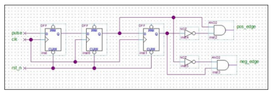
Therefore, when extracting the edge of an asynchronous signal, the above circuit cannot be used directly. Instead, the asynchronous signal should be synchronized first. Generally, one more register is used to reduce the probability of metastable state, as shown in the figure below :

Figure 2 Asynchronous signal edge detection
It can also be written in verilog, the code is as follows:
After such synchronization processing, the probability of the circuit entering the metastable state can be greatly reduced. If the first-level register enters the metastable state, it will generally stabilize within one clk cycle (it may be stable to 0 or stable to 1. ),As shown below:
To sum up, in the asynchronous signal edge detection circuit, at least three levels of registers are required to implement it. In digital systems that require higher system stability, more levels of registers can be used to reduce the probability of metastability. , Improve system stability.
If you want to know more, our website has product specifications for asynchronous signal edge detection circuit, you can go to ALLICDATA ELECTRONICS LIMITED to get more information

