What is the antenna technology of the new 5G system?
In terms of coupling reduction technology for terminal antennas, I propose a new coupling reduction technology suitable for terminal antennas. Using two or more coupled resonator networks, connected in parallel or cascaded on two antennas or multiple antennas, through a reasonable comprehensive design of network parameters, the effect of reducing the coupling of tightly coupled antennas and maintaining antenna matching can be achieved [12] ~[14], this kind of decoupling network is called "coupled resonator decoupling network". The main features of this network are:
1) Small size and easy to integrate. The latest type of decoupling network based on low-temperature co-fired ceramic technology can be packaged in 1608, which is very suitable for mobile terminals.
2) This network has a set of theories that can be comprehensively designed based on antenna parameters. Since the network parameters are controllable, the decoupling network can often achieve a relatively wide decoupling bandwidth.
3) The decoupling network does not depend on the antenna form and parameters. As long as the resonant frequency is determined, there is a set of mechanisms that can be adjusted to adapt to various antennas.
4) The parameter characteristics of the decoupling network itself ensure that the matching of the antenna itself will not be damaged during decoupling.
In order to meet the needs of the miniaturization of mobile terminal devices in 5G, we have adopted a low-temperature co-fired ceramic (LTCC) technology based on the 1608 package to implement the decoupling network. The dielectric constant of the material used is 9.8, with a total of 19 laminated layers. The schematic diagram is shown in Figure 1.
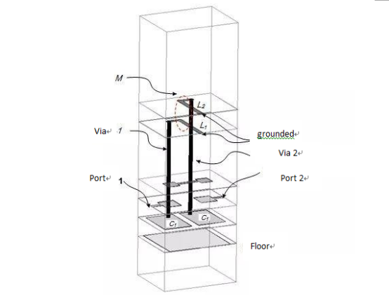
Figure 1. Two-stage coupled resonator decoupling network model implemented by LTCC
3 Coupling resonator decoupling network application examples We choose Wi-Fi 2.4GHz frequency band as an example to show the effect of coupling resonator decoupling network in actual antenna decoupling. Figure 2 (a) and (b) are the antenna with strong original coupling and the antenna after adding the coupled resonator decoupling network. The antennas are all made in the form of flexible printed circuit boards (FPC), and the antenna brackets are designed and processed by a 3D printer.
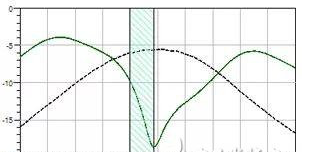
Before and after decoupling, the S-parameter comparison between the two antennas in Figure 2 is shown in Figure 3. It can be seen from Figure 3 that although the original coupled antenna is matched to meet the requirements, the isolation is only 5 to 6 dB, which shows that more than 25% of the energy is not effectively radiated, but is absorbed by another antenna load. After reasonably optimizing the design of the coupled resonator decoupling network, the isolation is increased to 10 to 15 dB when the matching state is not significantly deteriorated, and the coupled energy is already less than 10%. It can be seen that the coupled resonator decoupling network has an obvious effect on improving antenna isolation.
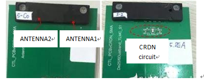
(a) (b)
Figure 2 (a) Coupled dual antennas (b) Decoupled dual antennas

(a) (b)
(c)
Figure 3. The amplitude response of (a) S11, (b) S22 and (c) S21 of the two antennas before and after decoupling
4 Metamaterial-based MIMO antenna array transformation technology is a brand-new concept. Man-made materials and structures such as metamaterials that have excellent electromagnetic properties and electromagnetic control capabilities can significantly improve antenna performance and expand its functions. Therefore, it has received extensive attention from inside and outside the industry and at home and abroad.
This research group has been paying great attention to metamaterial technology and its application in MIMO antenna arrays, and has continuously carried out relevant cutting-edge research and technology accumulation. Up to now, we have developed three antenna technologies that combine metamaterial technologies with MIMO antennas, antenna arrays and phased arrays. They are:
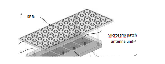
Figure 4
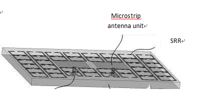
Figure 5
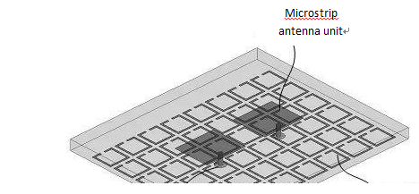
Figure 6
a. The metasurface is covered on the antenna array (Figure 4)
b. The antenna unit is embedded in the same layer of the metasurface (Figure 5)
c. Metasurface replaces the floor of the antenna array (Figure 6)
d. Each of these three types of technologies is applicable. It can be flexibly selected according to different antenna array forms and application scenarios (such as base stations, terminals, CPE equipment, etc.). It should be noted that the antenna and metamaterial structures in Figs. 5-6 are all schematic. In practice, other antennas and resonance structures can be used instead.
5 MIMO antenna array covering the metasurface. Take the microstrip antenna linear array as an example. After covering a layer of metamaterial surface at a suitable distance above the tightly coupled multi-element MIMO antenna array, microstrip antenna element 1 to microstrip antenna 2 The electromagnetic wave has three coupling paths:
①: Surface wave coupling
②: Space wave coupling
③: Man-made reflected wave coupling
Properly regulating the amplitude and phase of the coupling on the three paths can make the total effect of the coupling cancel each other out, thus effectively eliminating the mutual coupling between the units.
This research group has carried out physical verification on two microstrip antenna units working in the 5GHz frequency band. As shown in Fig. 7 and Fig. 8, Fig. 7 shows two microstrip antennas with strong coupling with each other. The physical distance between the two is only about 1mm, which is less than 0.02 times the free space operating wavelength.
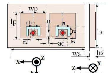
Figure 7. Two tightly coupled microstrip antennas
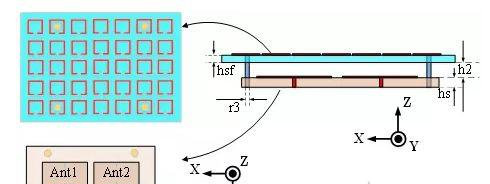
Figure 8. Two microstrip antennas with metasurfaces
After covering a metasurface composed of an open resonator ring, it can be seen that after the physical parameters of the metasurface are properly designed, the matching state of the two antennas has not deteriorated, and the isolation between the two antennas has increased to Close to 28dB, there is a total increase of 20dB.
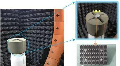
Figure 9. Microstrip antenna test setup with metasurface
In addition to the passive S-parameters, a significant improvement in performance can be seen from the metasurface. We also studied the improvement of the radiation characteristics of the entire microstrip MIMO antenna by the metasurface. The specific test status is shown in Figure 9. We tested the vector pattern of the two antennas in the laboratory's own SATIMO SG-24 system when they were excited, and saw the increase in antenna efficiency (Figure 10) and the envelope correlation coefficient (ECC) between the two antennas. Is significantly reduced (Figure 11).
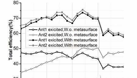
Figure 10. Two microstrip antennas without metasurface and with metasurface
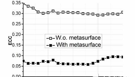
Figure 11. Envelope correlation coefficient between two microstrip antenna elements without metasurface and those with metasurface
6 MIMO antenna technology that uses metamaterials to replace antenna floors. Covering the surface of the antenna array with metasurfaces can significantly reduce the coupling between antenna elements and improve other antenna performance, but it will increase the antenna profile. This is in many applications. We don't want to see. Therefore, we have explored the possibility of embedding this layer of metamaterial into the traditional antenna floor, and got some exciting preliminary results.
As shown in Figure 11, we replaced the metal conductor floor of the original microstrip antenna with a mushroom-shaped (grounded) electronic band gap resonance structure (EBG) structure floor, and studied the antenna characteristics after the replacement. Research has found that this type of antenna array also has very low inter-unit mutual coupling (working in the 28GHz millimeter wave band), as shown in Figure 12. At the same time, while the unit is very compact, it has a very good phase sweep capability, as shown in Figures 13 and 14. It is very suitable for terminal use with phase scanning capability in 5G millimeter wave frequency band.
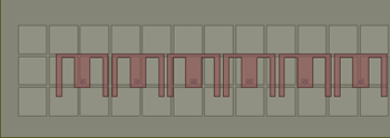
Figure 12. Eight-element microstrip antenna linear array using metamaterial floor
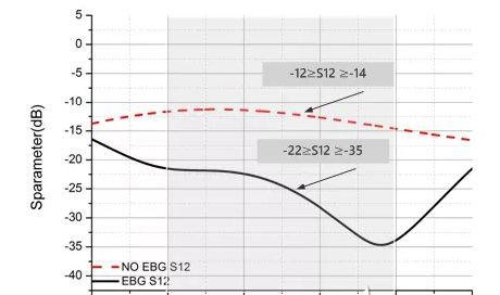
Figure 13. Isolation between two units in the antenna array with metal floor and EBG floor
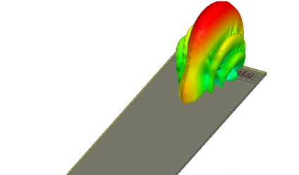
Figure 14. EBG floor eight-unit linear array phase scan
7 Summary and Prospects In addition to the technologies shown above, we have successfully proved that the technology covered by metamaterials can be applied to a larger number of elements, reducing coupling and improving performance of square arrays and dual-polarized antenna arrays. We also verified that the two-element microstrip antenna array surrounded by metamaterials can also achieve the purpose of reducing coupling. In the follow-up, this research group will commercialize the aforementioned technologies for more practical application scenarios. We will do our best for the further popularization and improvement of 5G technology.
If you need specific antenna, our factory can develop and produce it, please contact our email: selena@world-ic.com, alex@world-ic.com.

