How to use the analog switch of SPI interface to increase the channel density?
When the main goal of module development is to maximize the number of channels, board space becomes very precious. The switch is the key to increasing the number of channels in the system, but as the number of switches increases, the switch itself, logic circuits, and the devices required to generate these logic signals take up a lot of board space, reducing the available space. In the end, subject to the relevant factors required to control the switch itself, only a very limited number of channels can be achieved.
The most common solution to increase channel density is to use switches controlled by parallel logic signals. This requires a large number of GPIO signals, and a standard microcontroller cannot provide so many signals. In order to generate GPIO signals, one solution is to use a serial-to-parallel converter. These devices output parallel signals and are configured by serial protocols such as I2C and SPI.

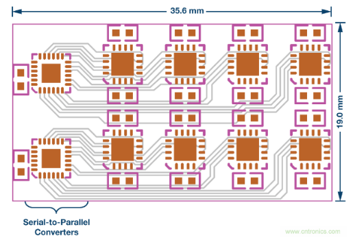
This solution demonstrates that the devices are daisy-chained. All devices share the chip select and serial clock digital lines from the SPI interface, and the first device in the daisy chain receives serial data. The data is then transferred to all devices in the chain (like a shift register). The size of this example solution is 30 mm x 18 mm and the area is 540 mm2.
Using the SPI interface in the form of a daisy chain can greatly reduce the board space occupied by serial-to-parallel converters and digital lines. With this switch configuration, the total circuit board area can be reduced by 20%, which greatly increases the channel density. The system platform has also been simplified. As the number of switches on the circuit board increases, the area saved increases, and a circuit board containing hundreds of switches can save more than 50% of space.
This shows that more switches can be placed in a smaller area. Compared with the traditional serial-to-parallel converter solution, the same area of the circuit board will support more channels.

Analog Devices' new SPI switch series can be used to achieve higher channel density. Through an innovative stacked dual-chip solution, ADI's current industry-leading precision switches can be configured using the industry standard SPI mode 0 interface. This means that not only can space be saved, but it will not adversely affect system performance.
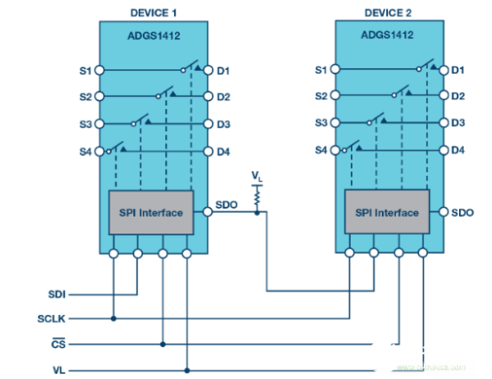
As mentioned above, the ADI SPI switch can work in daisy chain mode. ADGS1412 devices connected in a daisy chain configuration. All devices share the CS and SCLK digital lines, and the SDO of the device is connected to the SDI of the next device. Use a single 16-bit SPI frame to instruct all devices in the daisy chain to enter daisy chain mode. In daisy chain mode, SDO is an 8-cycle delayed version of SDI, so the desired switch configuration can be passed from one device in the daisy chain to another device.
When the device is in addressing mode or burst mode, it can detect protocol and communication errors on the SPI interface. There are three error detection methods, namely SCLK error count, invalid read and write addresses, and up to 3 bits of CRC error detection. These error detection functions ensure that the digital interface can work reliably even in harsh environments.
If you want to know more, our website has product specifications for switch, you can go to ALLICDATA ELECTRONICS LIMITED to get more information

