What is the difference between magnetic beads and inductors in solving EMI and EMC?
Magnetic beads are designed to suppress high-frequency noise and spikes on signal lines, power lines, and the ability to absorb electrostatic pulses. Magnetic beads are used to absorb ultra-high frequency signals, such as some RF circuits, PLLs, oscillating circuits, and ultra-high-frequency memory circuits (DDRSDRAM, RAMBUS, etc.), which need to add magnetic beads to the input part of the power supply, and the inductor is an energy storage device. Components, used in LC oscillator circuits, low-frequency filter circuits, etc., whose application frequency range rarely exceeds 50MHZ. Magnetic beads have high resistivity and magnetic permeability, equivalent to series connection of resistance and inductance, but resistance value and inductance. Values vary with frequency.
The function of the magnetic beads is mainly to eliminate the RF noise existing in the transmission line structure (circuit). The RF energy is an AC sine wave component superimposed on the DC transmission level. The DC component is a useful signal required, and the RF RF energy is useless. Electromagnetic interference is transmitted along the line and radiated (EMI). To eliminate these unwanted signal energies, use a chip bead to act as a high frequency resistor (attenuator) that allows the DC signal to pass through and filter out the AC signal. Usually the high frequency signal is above 30 MHz, however, the low frequency signal is also affected by the chip bead. Magnetic beads have a high electrical resistivity and permeability, which is equivalent to the series connection of resistance and inductance, but both resistance and inductance values vary with frequency. He has better high-frequency filtering characteristics than ordinary inductors and resistive at high frequencies, so it can maintain high impedance over a wide frequency range, thus improving the frequency modulation filtering effect.
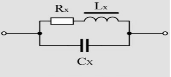
The magnetic bead can be equivalent to an inductor, but the equivalent inductance is different from the inductive coil. The biggest difference between the magnetic bead and the inductive coil is that the inductive coil has a distributed capacitance. Therefore, the inductor is equivalent to an inductor in parallel with a distributed capacitor. As shown in Figure 1. In Figure 1, LX is the equivalent inductance (ideal inductance) of the inductor, RX is the equivalent resistance of the coil, and CX is the distributed capacitance of the inductor.

Fig.1 Inductive coil equivalent circuit
Inductors (inductor coils) and transformers are electromagnetic induction components wound with insulated wires (such as enameled wire, yarn wrapped wire, etc.), and are also commonly used components in electronic circuits, such as common mode filters. When a current flows through the coil, a magnetic field is generated around the coil. When the current in the coil changes, the surrounding magnetic field also changes accordingly. The changed magnetic field can cause the coil itself to generate an induced electromotive force (the electromotive force is used to indicate the terminal voltage of the ideal power source of the active component), which is self-inductance. When the two inductor coils are close to each other, the change in the magnetic field of one inductor coil will affect the other inductor coil. This effect is mutual inductance. The magnitude of the mutual inductance depends on the degree to which the inductance of the inductor is coupled to the two inductors. The component made by this principle is called a transformer.
Theoretically, the conducted interference signal is suppressed, and it is required to suppress the inductance of the inductor as much as possible. However, for the inductor coil, the larger the inductance, the larger the distributed capacitance of the inductor coil, and the roles of the two will cancel each other out.

