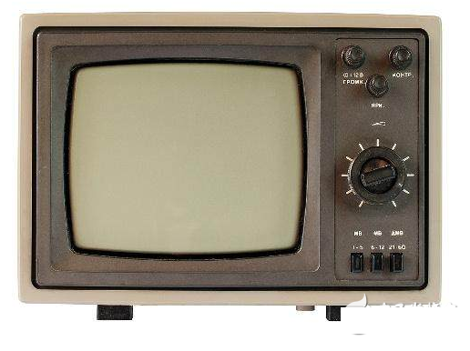
What is the circuit of the video amplifier?
Video Amplifier is an amplified video signal that enhances the brightness, chrominance, and sync of the video. When the video transmission distance is relatively long, it is better to use a video line with a thicker line diameter, and at the same time, a video amplifier can be added in the line to enhance the signal strength to achieve long-distance transmission. The video amplifier can enhance the brightness, chrominance and sync signal of the video, but the inter-line interference signal will also be amplified. In addition, too many video amplifiers cannot be connected in series in the loop, otherwise saturation will occur and the image will be distorted.
Although the video amplifier is similar to the audio amplifier in the radio, its requirements are relatively high, and the following points need attention. The first point, unlike an audio amplifier, is not a power amplifier but a voltage amplifier, and its final stage has a large voltage output in order to get enough contrast in the picture tube. Second, its output voltage polarity is correct in order to get a normal image. Third, in order to obtain high-quality images, the frequency distortion of the amplifier must be small over a wide frequency range from 50 Hz to 6 MHz. The high-frequency component is equivalent to the horizontal detail of the image, when the high-frequency component is insufficiently amplified. The subtle changes in the image are invisible and the resolution is poor. At this time, even if the focus is good, the raster scan line is clear, the number of lines that can be seen in the vertical wedge beam on the test chart is still reduced, and the transition between the black and white of the vertical contour of the image is also blurred (ie, the edge is blurred or the area is blurred). ), and there will be short smear.
Capacitively coupled video amplifying circuit
When the video is powered by 100V, the collector voltage of the viewing tube is 55 to 70V, which is a normal range. Some models use a pre-view and direct-coupled view, so the operating point of the view is determined by the pre-view bias circuit. Most of the pre-view bias of such circuits is not separate, but is biased in series by the AGC tube. If the AGC has been adjusted, and the pre-view should also meet the requirements, it is generally not necessary to readjust the original bias circuit. But what must we do to adjust? When the collector voltage of the apparent discharge tube is high, the resistance of the emitter can be reduced, and when it is low, the emitter resistance can be increased.
3, adjustment of cathode beam current

Connect an ammeter to the cathode and replace it with an external potentiometer. After turning on the power, set the contrast to the appropriate position, adjust the brightness potentiometer to the middle position, and then adjust the external potentiometer to make the negative beam current the rated value for 35cm. The following are generally 90uA----120uA, the maximum is no more than 140uA, for 40cm or more. It is 100uA to 130uA and the maximum is no more than 150uA.
If the current in the cathode beam has reached the rated value and the brightness is still not bright enough, it should be checked whether the acceleration pole and the cathode high voltage are sufficient. If they meet the requirements, it means that the picture tube has deteriorated and cannot be used any more!
If you want to know more, our website has product specifications for the video amplifier, you can go to ALLICDATA ELECTRONICS LIMITED to get more information

