Application of the operational amplification
1. Operational amplifiers
The operational amplifier is used in the main board to control the operation of the MOS tube. The output end of the operational amplifier is connected to the G pole of the MOS tube to control the voltage of the MOS tube, and the voltage of the control pole is adjusted by feedback to make the S pole of the MOS transistor output a stable voltage.
The most common operational amplifiers on the motherboard are LM358,LM324,AZ324,LM393 and so on.
There are two separate operational amplifiers inside the LM358 chip. The physical object is shown in figure 1. The LM358 pin definition is shown in Fig.
2. The IN1 (+) pin is the in-phase input terminal, INI (-) the IN1 pin is the inverse input terminal and the OUTI is the output terminal.

Fig.1 LM358 object Fig.2 LM358 Pin arrangement diagram
Working principle: when the phase input terminal voltage is higher than the reverse phase input terminal voltage, the output high level. On the other hand, when the voltage of in-phase input terminal is lower than that of inverse-phase input terminal, the output is low level.
LM324 integrates 4 independent comparators, the physical and foot positions are arranged as shown in Fig. 3and Fig. 4. INPUT is the input pin, OUTPUT is the output pin, vcC is the power supply, and GND is the ground.

Fig.3 LM324 object Fig.4 LM324 Pin arrangement diagram
2. Application of operational Amplifier.
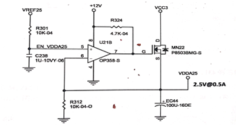
As shown in figure 5, the 2.5V voltage of VREF25 is changed to the in-phase input of U2IB by EN_VDDA25, after the resistor R301, with a voltage of 5 feet higher than 6 feet, a high output level of 7 feet, a slow conduction of MN22, and a slow increase of VDDA25 voltage. And return to U21B through the line of 6 feet, and 5 feet in the internal comparison. When the output voltage of MN22 is up to 2.6 V, the output voltage of 6 pods feedback to U21B is higher than that of 5 feet, and the output voltage of 7 pods is low, and the output voltage will decrease slowly when the output voltage of MN22 is cut off. When the output voltage drops to 2.4V, the five-pin voltage is higher than the six-foot voltage, and the 7-pin output high level MN22. is switched on again. Under the control of U21B, the MN22 cycle conduction can be filtered by the S-pole filter capacitor EC44 filter of MN22, the fluctuation of 2.6V 2.4V can be filtered, and the output of 2.5V VDDA25 power supply can be stabilized.

Fig.5 VDDA25 supply circuit
If you want to know more, our website has product specifications for operational Amplifiers, you can go to ALLICDATA ELECTRONICS LIMITED to get more information.

