How is RFID long-range read-write antenna designed?
1 Introduction
Radio frequency identification RFID (Radio Frequency Identification) is a non-contact automatic identification technology using radio frequency communication. It uses the spatial coupling of radio frequency signals to transfer non-contact information, and identifies objects through the transmitted information. RFID solves the two major problems of passive (no power in the card) and contactless, and realizes moving target recognition and multi-target recognition. Its outstanding advantages are strong environmental adaptability, ability to penetrate non-metallic materials, large data storage, and anti-interference ability Strong. Current readers are far from meeting application requirements. Therefore, a long-range reader is required to cooperate with a long-range antenna to achieve long-distance horizontal or vertical read-write requirements. Here is a design solution for a long-range RFID read-write antenna. The RFID tag reader-writer RI-R6C-001A is used. This device requires an antenna impedance of 50 Ω and a frequency of 13.56 MHz. Therefore, it is simple and low. Cost of PCB loop antenna.
2 RFID read and write antenna design
2.1 RFID reader antenna working principle
An antenna is a device that transmits and receives radio frequency carrier signals. Under the condition that the operating frequency and bandwidth are determined, the antenna transmits the RF carrier generated by the RF processing module and receives the RF carrier transmitted or reflected from the tag. Its role is to generate magnetic flux, provide power for the tag (passive), and read and write. Information between the reader and the tag. The performance of the antenna plays a key role in the overall performance of the system. The reading and writing distance of an RFID antenna depends on many factors: the size, directivity, location of the antenna, electrical characteristics of the frequency band, and the surrounding environment.
2.2 RFID performance parameters
2.2.1 Directionality of electronic tags
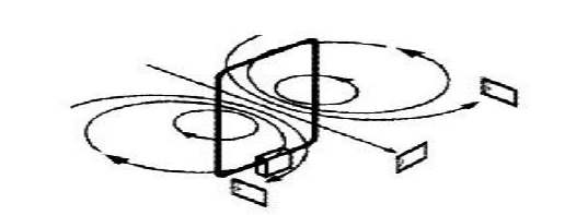
Since the passive electronic tag obtains energy by coupling with the magnetic field of the reader antenna, the directivity of the tag directly affects the coupling coefficient, and recently affects the energy acquisition and communication reliability. When the directivity of the tag and the reader antenna are optimally coupled, the magnetic field lines are at right angles to the electronic tag. Electronic tags can get the best reading and writing results. However, if the electronic tag is moved to both sides of the antenna, the placement position of the tag is parallel to the direction of the magnetic field lines. At this time, the directivity is the worst, and the reading and writing effects are also the worst. Figure 1 is a simulation diagram of the magnetic field line distribution of the antenna.

2.2.2 Antenna Blind Zone
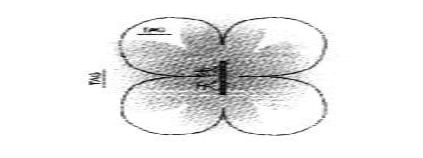
Because the electromagnetic field of the loop antenna is unevenly distributed in its vicinity, a blind zone for reading and writing will occur. The area outside the area outlined by the black line in FIG. 2 is generally a read-write blind area of a single antenna. Repeated experiments have shown that when the placement position of the electronic label is turned to an angle of 40 ° from the optimal position, normal reading and writing operations are generally possible.

2.2.3 Antenna quality factor Q
For antennas of inductively coupled RFID systems. In the case of constant size, a larger Q value means a larger current intensity in the antenna coil, a stronger output power, and a longer read-write distance. The formula for the figure of merit Q is:

Where f0 is the operating frequency (13.56 MHz), L is the equivalent inductance of the antenna, and R is the equivalent parallel resistance of the antenna. The antenna bandwidth B is easily calculated from p:

It can be seen from equation (2) that the transmission bandwidth B of the antenna is inversely proportional to the quality factor Q. Therefore, an excessively high figure of merit will result in a reduction in bandwidth and a decrease in the amplitude of the modulation sideband signal of the reader, resulting in the reader being unable to communicate with the tag. The relationship between the antenna Q value and the 3 dB bandwidth is shown in Figure 3. It can be seen from Figure 3 that when the loop antenna is connected to a 50 Ω load, its Q value is preferably not more than 30. To optimize the performance of the antenna. The standing wave ratio of the reader's matching circuit should be less than 1: 1.2.
After the antenna design is complete, use a vector network analyzer to measure the antenna quality factor and bandwidth. If the bandwidth does not meet the requirements, a parallel resistor can be added for adjustment.
Let the antenna's resonant resistance be Rpor and the ideal figure of merit be Qreqtuired, then:

Assuming the antenna quality factor measured by the spectrum analyzer is Qreqtuired, the impedance of the corresponding antenna is:

The final antenna needs a parallel resistor R:

In this design, the antenna quality factor is designed according to the above steps, and Qrequired = 30.
2.2.4 Antenna size
Under normal circumstances. The recognition distance of the reader is related to the antenna device and magnetic field strength of the reader. The larger the antenna, the larger the output power, and the longer the reading distance. However, as the size of the antenna increases, other problems also arise: the signal-to-noise ratio decreases; in order to comply with the requirements of electromagnetic compatibility standards at home and abroad, electromagnetic shielding measures may need to be implemented; The blind spot electronic tag cannot respond: the matching problem between the antenna of the electronic tag and the antenna of the reader is more difficult to solve. If the inductance is too large, it may not even be solved. There is a limit between the maximum geometric size of the antenna and the operating wavelength, which is generally defined as:

Where L is the maximum size of the antenna and λ is the operating wavelength.
For a 13.6 MHz RFID system, the maximum antenna size should be about 50 cm. Use size 50 cm × 50
cm single antenna reader, when the radiated power reaches 0.8 W, it can achieve an effective read and write distance of 50 cm. With dual antennas, an effective read-write distance of more than 1 m can be achieved.
2.2.5 Matching Network
The RFID reader frequency studied in this article is 13.56 MHz. In order to effectively suppress high-frequency effects such as power reflection and parasitic radiation, the reader antenna is usually connected to the reader's high-frequency module through a coaxial cable. The coaxial cable impedance 50 Ω. Therefore, the impedance matching of the antenna is to change the input impedance of the reader antenna through a certain passive matching circuit to make it consistent with the impedance of the coaxial cable, so that energy can be read from the coaxial cable without loss. The writer transmits it. Figure 4 shows the circuit of an inductively coupled radio frequency identification system using 50 Ω technology.
3 Conclusion
The key to the RFID reader's long-distance reading and writing function lies in the design of the antenna. By studying the working principle and performance parameters of the RFID antenna, an effective antenna design optimization scheme is proposed, so that the reader has a longer reading and writing distance. And higher energy utilization. The experiment proves that the RFID reader with the optimized long-range RF antenna can achieve a reading and writing distance of 30 cm.
If you want to know more, our website has product specifications for the RFID, you can go to ALLICDATA ELECTRONICS LIMITED to get more information

