GIGABYTE Motherboard Point Bitmap usage.
1. Introduction to Point Bitmap Viewer.
Gigabyte motherboard point bitmap opening software is using Academi, to run the program is fabview.exe, as shown in figure 1.

Fig.1 Academi Point Bitmap programs and Files
2. Point bitmap installation.
Step 1 double-click the software icon shown in figure 1 to run the program, followed by the program run interface shown in figure 2.
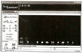
Fig.2 Program running interface
Step 2, click the button to find the location of the program source, as shown in figure 3.
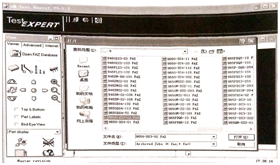
Fig.3 finds the point bitmap program source interface.
Step 3, select the corresponding program source and click the Open button to load the program source to display the motherboard components, as shown in figure 4.
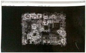
Fig.4 point bitmap program source loading interface.
Step 4: press P to display the window shown in figure 5.
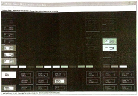
Figure 5 set the interface
Step 5, right-click over L51, L50, and remove green and orange, as shown in figure 6.
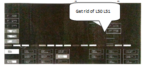
Figure 6 setup Interface 2
Step 6, click Edit-Escape Esc to exit the settings, the display will be clearer, as shown in figure 7.
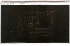
Fig.7 Set post-effect diagram
3. Feature button description.
T key: displays the front, which is preset to blue.
B key: displays the opposite side, the reverse default is red.
P key: set the key, you can set the relevant color.
4. Component lookup method.
Step 1, click the component search button to pop up the component search dialog box, as shown in figure 8.
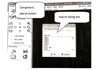
Figure 8 Meta device search dialog box.
Step 2, in the component search dialog box, enter the location number that you need to find the component, as shown in figure 9.
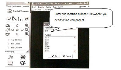
Fig. 9 device position number input.
Step 3, select the location number corresponding to the component you want to find, and then click the OK button, where the self-colored location of the found component is shown, as shown in figure 10.
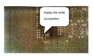
Fig. 10 device location display diagram.
Step 4, click the corresponding component, and then display the parameters of the checked component in the lower-left corner, as shown in figure 11.
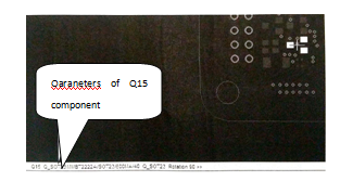
Fig. 11 the parameter of the device is
5. Signal lookup method.
Step 1, single-click the network line search button shown in figure 12 to pop up the signal search dialog box.
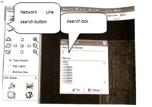
Figure 12 signal search dialog box .
Step 2, enter the name of the signal that needs to be looked up, as shown in figure 13.
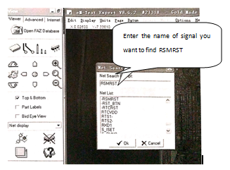
Figure 13 input to find the signal directly.
Step 3, select the corresponding signal name and click the OK button to display the white line for the searched signal, as shown in figure 14.
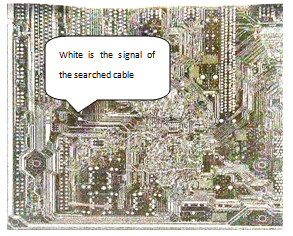
Fig.14RSMSRT signal connection diagram
6. Connection point lookup method.
Step 1, right-clicking on the component pin displays the connected position with a white line, as shown in figure 15.
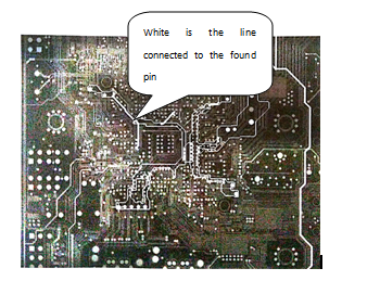
Figure 15 connected point diagram
Step 2: click the snap button to display the next connection point or the location of the connected components, as shown in figure 16.
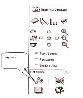
Figure 16 capture button.
Step 3 Click the reset button to clear all marked lines (see figure 17).
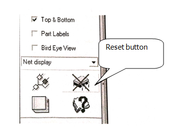
Figure 17 reset Button
This article is from Allicdata Electronics Limited.

