How the Intel G41 chipset motherboard works?
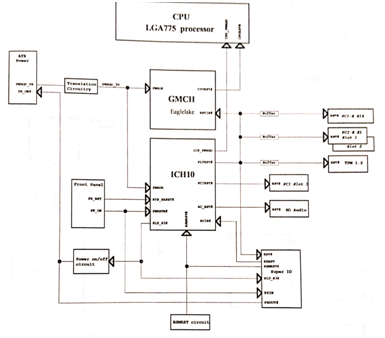
The IntelG41 chipset dual-core motherboard works as shown in figure 1.

Figure 1 schematic diagram of the Intel G41 chipset dual-mode motherboard.
The IntelG41 chipset dual-core motherboard works as follows.
①The 10 chip sends a RSMRSTST# signal to the South Bridge chip, indicating that the motherboard standby power supply is normal.
②The short switch generates a SW_ON trigger signal, one to the PSIN pin of the IO chip, and the other to the PWRBTN# pin of the South Bridge chip to request power (some motherboards are supplied to the IO chip by the switch pin). After the internal conversion of the IO chip, the PWRBTN# signal is outputted to the Nanqiao chip to request power on).
③The South Bridge chip sends a continuously high-level SLP_S3# signal back to the IO chip to indicate that power is allowed.
④The IO chip receives the SLP_S3# signal, sends out the continuously low power PSOUT# signal through the internal conversion, and sends the PS ON pin to the ATX power supply to the low green cable.
⑤The green cable is pulled down and turned on and the output is + 12V, + 5V, + 3.3V. The output is + 12V, + 5V, + 3.3V.
⑥The ATX power delay sends out a 5V high-level PWRGD_PS signal. After the conversion circuit, it is renamed PWRGD_3V, to the PWROK pin of the South Bridge chip and the North Bridge chip, indicating that the power supply voltage is normal.
⑦After the PWRGD _ PS high level is received by the South Bridge chip and the clock signal is normally received, the CPU _ PWRGD signal is sent to the CPU, to indicate that the motherboard is powered properly.
⑧ South Bridge chip output platform reset signal PLTRST#, sent to 1O chip, TPM, PCI-E slot, North Bridge chip to power on the reset.
⑨The South Bridge chip generates a PCIRST# signal to reset the PCI slot.
⑩The South Bridge chip simultaneously issues the AC_RST# reset sound card chip. 11.North Bridge chip power supply, clock signal, PWRGD_PS normal, received PLTRST# platform reset signal, internal delay to send CPURST# signal reset CPU, CPU to start work.
This article is from Allicdata Electronics Limited. Reprinted need to indicate the source.

