How to make a wireless music doorbell?
The production of wireless music doorbell has been introduced in many electronic newspapers and magazines, and there are also many music chips in the market with multiple tunes, considering that most beginners have not been exposed to music chips. It is very easy to damage music integrated circuits in production. This article introduces the multi-tune music film, belongs to the special chip. In order to improve the practical ability of the beginners and the level of electronic technology, the circuit adopts the universal music chip as the basis of the music circuit. Using the most commonly used BJ-15 or 9300 music chip on the market to promote the sound device to sound.
1.Introduction of Circuit principle.
Schematic diagram of radio chord music doorbell circuit is shown
in Figure1 and Fig.2.
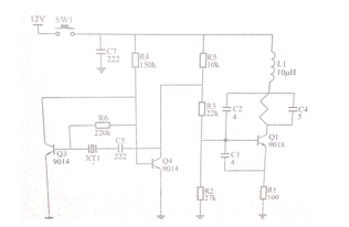
Fig.1 Schematic diagram of radio chord music doorbell circuit.
This paper briefly introduces the principle of transmitting circuit. Q3, Q4, XT1 and other components constitute low frequency signal oscillation circuit, whose frequency value is determined by crystal oscillator XT1, C5 and so on. Q1, C1, C2, C4 and other components constitute three-point capacitor high frequency oscillation circuit. The signal generated by the low frequency signal is injected into the base of Q1 by R3, and the high frequency signal is modulated. The modulated carrier signal is transmitted from the antenna on the circuit board to the air, which is used as the remote control signal of the wireless remote control doorbell.
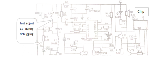
Fig.2 Receiving circuit schematic
VT1 and related components constitute super-regenerative detection circuit. L1 and C4 constitute frequency selective network. When the parallel resonant frequency of L1 and C4 is the same as the transmitter, the impedance is the largest and the maximum gain is obtained, while the radio signal of other frequencies is due to detuning. Will not be effectively magnified and thus suppressed. The transmitted remote control signal is output from the parallel resonant end after super-regenerative detection, and is fed into the non-gate circuit by R4 and C6 coupling to amplify. After the two-stage negative feedback amplification, the output is from the 6-pin output of IC1, and the XT1, VT2 and so on constitute the frequency selective amplifier circuit. The resonant frequency of the receiving circuit is the same as the modulation frequency of the transmitter. Only the signal transmitted by the transmitter has the smallest impedance, while the other interference signals exhibit higher impedance and attenuate seriously. The control signal transmitted by the transmitter is received by the frequency-selective network circuit and is latched by a monolithic circuit composed of VD2, RI1, C11, etc., which controls the VT4 conduction, sends a trigger signal to the music circuit 1C2, and makes the music circuit work and play a piece of music. When a song is finished, if you don't press the transmitter again, the music stops and the system automatically enters the waiting state.
2.Circuit fabrication.
When welding the transmitter circuit board, the emitter can be assembled according to the symbol diagram on the circuit board. The C3 mark on the transmitter circuit board is the position left by compensating the power capacity and does not actually need to weld any parts, so the circuit schematic is not marked. After installing the transmission circuit.
When welding the receiver circuit board, the assembly can be completed only by comparing the schematic diagram of the symbols on the circuit board, in which the R9 in the circuit diagram is reserved for the function test. and the actual installation is not required, and there is no 1MΩ resistor in the component. The LED welding height must be determined in conjunction with the height of the housing, and when the lid is properly covered, it will be level with the housing. The receiving board after the components are installed is shown in figure 3.
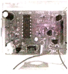
Fig.3Acceptance board
Welding power and horn wiring, as shown in figure 4.
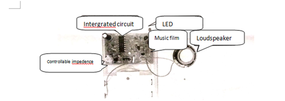
Fig.4Welding power source and la
4.System Debug
Debugging of the transmitter: after all the components are installed, put the circuit board in the box of the remote control, and pay attention to check whether the fretting switch can hear the clear sound of the switch.
(2)After loading the transmitter battery, press the remote controller to detect whether there is a high frequency radio wave emission, usually with radio or connected to the computer sound. When pressing the remote controller, you can hear the "crunching and squeaking" sound, which indicates that the transmitting part is working normally. In general, as long as the components are installed correctly, when the components are welded, there is no continuous welding or virtual welding on the circuit board, which can be successful at one time.
(3)receiver debugging: after all the components are installed, the circuit board shall be mounted into the plastic outer competing shell, and the polarity must not be reversed when the power lead is connected.
Install two No. 5 batteries, briefly connect VT4 emitter and collector, normally you can hear the music sound, if you find no sound, you should carefully check whether the horn wire is welded firmly, whether there is virtual welding on the pin of the music piece, etc. If the above items are normal, the transmitter can be combined with the receiver, and the transmitter will be placed on the side of the receiver, and the remote controller will be moved. If there is a sound, the distance between the two can be increased, and then press, if there is no response, The adjustable inductance on the receiver is adjusted with a sensorless screwdriver until the remote control receiver will ring and continue to increase the distance. The method mentioned above is repeatedly debugged. When the distance is above 20m, the remote control can be reliably carried out. It shows that the remote control doorbell is finished, and the wireless music doorbell is finisheD,as shown Fig.5
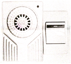
Fig.5 Assembled doorbell
This article is from Allicdata Electronics Limited. Reprinted need to indicate the source.

