Intel single Bridge Motherboard bus Power supply Analysis.
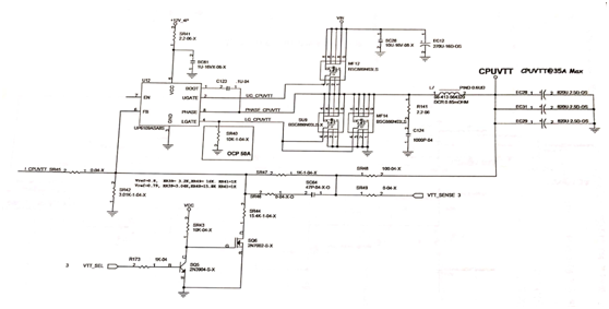
The bus power supply of the Intel single-bridge motherboard is very different from the previous dual-bridge motherboard. Dual-bridge motherboard basically uses operation plus MOS tube linear step-down to provide bus power supply, and single-bridge motherboard bus power supply current needs to be relatively large, so bus power supply is basically generated by PWM switching power supply step-down mode. The circuit controlled by the UP6109 chip to generate CPUVTT bus power supply is shown in figure 1.

Fig.1 generate CPUVTT bus power supply
1. After the SR41 current limit, the main power supply of + 12V_4P supplies power to the UP6109, and the chip gives one pin of power supply inside the chip. At the same time, the capacitor C123 is charged at the same time.
2. Chip internal pull-up gives 7 feet a high level.
3. After the working conditions of VCC, BOOT and EN are normal, the chip outputs UG_CPUVTT high level from two pins, MF12 is on, and VIN is supplied with stable CPUVTT bus through MF12 step-down through inductor and capacitor filter.
4. CPUVTT is fed back to UP6109's FB pin via SR48, SR47, and SR42 in series.
5. When the output voltage is raised and the voltage value after the split voltage is higher than 0.8V, the chip will close the 2-pin UG_CPUVTT output, turn on the 4-pin output high level, MF14 on, the load is powered by the back-stage inductance and capacitor, and the circuit is formed through the MF14. When the feedback voltage is less than 0.8V, the chip turns off the MF14, and turns on the MF12. In such a cycle, the power supply is powered by a stable CPUVTT bus output through a post-capacitor filter.
This article is from Allicdata Electronics Limited

