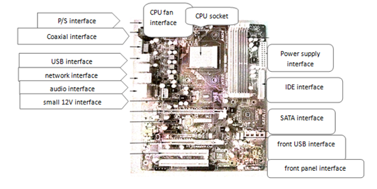
What are the interfaces on motherboards?
The interfaces on the motherboard are shown in figure 1.

Fig.1 SATA interface
1.SATA Interface
The SATA interface (figure 2) is the current mainstream hard disk interface for connecting serial hard drives and optical drives. The motherboard is usually equipped with 4 ~ 8 SATA interfaces. The speed of SATA 2.0 interface can reach 3GB / s, which is faster than that of IDE interface. Some motherboards also have SATA2.0 and SATA3.0 interfaces.

Fig.2 SATA interface
2.Power Interface
Motherboard power interface is divided into main power supply interface and small 12 V interface. The main power supply connection (Fig.3) is the common 20 / 24 pin interface.Including +12V,,+5V,+3.3V,-12V,5VSB, power supply good signal, PSON start signal, is the main source of mainboard power supply.Small 12V interface, also known as small 4P interface (figure 4), is a CPU independent 12V power supply interface.

Fig.3 ATX 24 pin interface Fig.4 small 12V interface
3.Fan interface
When the motherboard works, CPU, North Bridge Chip, South Bridge Chip will generate heat. In order to prevent chip damage, the heat-emitting chip plus cooling fan for heat dissipation. The common CPU fan interface (see figure 5, represented by CPU_FAN > is used to connect the CPU fan, and the system fan interface (see figure 6, shown in SYS_FAN) is used to connect the cooling fan other than the CPU fan. There is only one system fan on the main board ofIntel and DELL brand machine. When the fan is not connected, the error will be reported when the fan is turned on. The ordinary motherboard without CPU fan will also report the error, and will prompt F1 to notify the user to install the fan.

Fig.5 CPU fan interface Fig.6 system fan interface
4.P/S2 Interface
The P/S2 interface (see figure 7) is mainly connected to the keyboard and mouse that are commonly described. Green for the mouse interface, blue for the keyboard interface. Some motherboards already use a two-in-one interface (see figure 8). Only one P/S2 interface device can be used and the other must use the USB interface. The new motherboard is no longer suitable for the P/S2 interface, all of which use the USB interface.

Fig.7 P/S2 interface Fig.8 P/S2 two-in-one interface
5.Video output interface
A video output interface is used to transmit video signals to display devices, such as displays, televisions, projection, etc. Common video output interfaces on the motherboard are the VGA analog interface (see figure 9), the DVI digital interface (see figure 10), and the HDMI high-definition multimedia interface (see figure 11). The output of the DVI interface is a digital signal, and most displays now have an VGA analog interface, so DVI usage is lower than the VGA interface. HDMI interface also known as high-definition interface, transmission signals including video and audio data, in the motherboard has gradually become popular.

Fig.9 VGA interface Fig.10 DVI interface Fig.11 HDMI interface
6.USB Interface
USB interface is used to connect digital product devices, such as mobile hard disk, mobile phone, wireless mouse, wireless keyboard, etc. It is the most used interface of all interfaces of motherboard. USB interface is divided into front USB interface and post USB interface. The front USB floor is connected to the front USB pin on the main board by connecting wire (see Fig. 12), and the rear USB interface (see Fig.13) is fixed to the motherboard.
7.Network Interface
Network interface (figure 14) is also called network cable. The host is connected to the network via a network interface and network cable. There are green lights and yellow lights on the interface, the green light will shine when plugging in the internet line, and the yellow light will flash back when there is data transmission.

Fig.12 the front USB pin Fig.13 the rear USB interface Fig.14 Network interface
8.Audio Interface
The audio interface (see figure 15) is an interface that supports input and output, including audio output, audio input, and microphone input. Audio output to power amplifier and input signal from microphone are realized through audio interface. Some motherboards support 5.1 or 8.1 channels, using a six-hole audio interface (see figure 16).
9.Front panel pin
The front panel pin (figure 17) is a pin connecting the front control part of the chassis. The pin arrangement includes power switch, which is indicated by PS,PW,SW,PSON, reset switch by RST, power indicator by PW_LED and hard disk indicator by HDD_LED.

Fig.15audio interface Fig.16 six-hole audio interface Fig.17 front panel pin
10.CMOS Jumper
The CMOS jumper (see Fig.18), also known as the discharge jumper, refers to a jumper that provides a reset signal for the RTC circuit inside the Nanqiao chip. The common three needles are divided into normal mode and clearance mode, jumper cap in 1-2 pin for normal mode, jumper cap in 2-3 pin for clearance mode (that is, often said to discharge). There are only two jumpers in the Gigabyte motherboard (Fig.19). Jumper cap isn't installed in normal working condition, when it is necessary to remove the jumper cap from CMOS fashion.

Fig.18 CMOS Jumper Fig.19 Gigabyte motherboard jumper
11.USB、P/S2 Power supply jumper
Part of the main board there is a USB,P/S2 power supply jumper (figure 20), mainly to achieve keyboard boot function. By means of jumper wire setting, the keyboard can be powered by the mainboard without power, and the user can set it up according to his own needs.

Fig.20 USB Power supply jumper
This article is from Allicdata Electronics Limited. Reprinted need to indicate the source.

