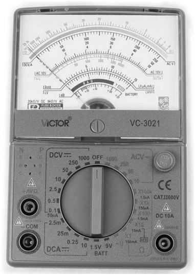
What is the structure of a common mechanical multimeter?
The ordinary mechanical multimeter is composed of a meter head (magnetic type), a gear shift switch, a mechanical zero adjustment device, a potentiometer, a test lead, a socket, and the like.
According to the form of rotary switch, it can be divided into two categories: one is single rotary switch type, such as MF9 type, MF10 type, MF47 type, MF50 type, etc. The other type is double rotary switch type, commonly used is MF500 type. The shape of the mechanical multimeter is shown in Figure 1.

Figure 1 The shape of the mechanical multimeter
1. Circuit part.
The multimeter consists of 5 parts of circuits, which are respectively:
1) A header or header circuit for indicating the measurement result;
2) A voltage divider circuit for measuring AC and DC voltages;
3) A shunt circuit for measuring DC current;
4) battery zero potentiometer, etc., used to measure resistance;
5) Measurement selection circuit for selecting the range of the gear.
2. Header
A magnetoelectric micro-ampere meter is used as the meter head. The inside of the meter head is composed of upstream and downstream wires, magnets and the like. When a small current passes through the meter, electromagnetic induction is generated, and the coil rotates under the action of the magnetic field and drives the pointer to deflect. The amount of deflection of the pointer depends on the amount of current through the meter. Since the wire diameter of the head coil is relatively small, the current allowed to pass is small. In practical applications, in order to meet the needs of a larger range, a shunt and a step-down circuit are provided inside the multimeter to complete measurement of various physical quantities.
3. Dial
The first tick mark is an electrical blocking reading. Its right end is“0”and the left end is “∞ (infinity)”, and the tick marks are uneven. The reading should be read from right to left, that is, the closer the needle is to the left end. The greater the resistance.
The 2nd and 3rd scale lines are readings of AC voltage, DC voltage and DC current. The left end is “0” and the right end is the maximum reading. Depending on the range switch, even if the pointer is placed in the same position, the values of the voltage and current indicated are different.
The fourth scale line is the AC voltage reading line, which is set to improve the accuracy of the small voltage reading.
The fifth scale line is the transistor amplification (hFE) block.
The 6th scale line and 7th scale line are the reading lines for measuring the load current and the load voltage, respectively.
The 8th scale line is the reading line for the audio level (dB).
This article is from Allicdata Electronics Limited. Reprinted need to indicate the source.

