ASUS Host Point Bitmap usage method 1
1. Introduction to the point bitmap.
The spot bitmap is the location map of the components on the motherboard, which is used to describe the location and parameters of the components on the motherboard, to facilitate people to find the corresponding location of the components, and to improve the maintenance efficiency. So learning to check bitmap is also a key point to learn mainboard maintenance. During maintenance, most of the ASUS motherboards can find the corresponding point bitmap.
2. Point bitmap software installation.
TSICT Point Bitmap software is a green version of software that runs directly without requiring installation. As a reminder, the TSICT.exe program and the tsict.inf file must be in the same folder to run the program, as shown in figure 1.
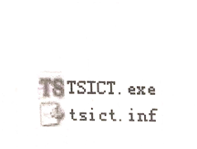
Fig.1 TSICT program file
Double-click TSICT.exe directly to run the program, and then click the Model main menu to load the point bitmap file you want to open, as shown in figure 2.
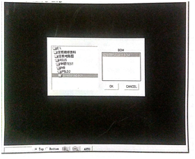
Fig.2 Select the point bitmap file you want to open
Click the corresponding Motherboard Model to select the corresponding barcode for the motherboard, click the catalog in the BOM box, and finally click the OK button to load the point bitmap file. Figure 1 / 133 shows the loaded P5LD2 motherboard point bitmap.
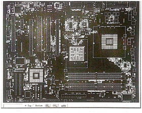
Fig.3 P5LD2 Motherboard Point Bitmap
3. Tool description.
At the left pin of the window, there is a toolbar that contains the lookup box, the top and bottom toggle selected single options, the zoom in and out buttons, and the ATUO automatic size button, as shown in figure 4.

Fig.4 Tool description
4. Component lookup method.
Step 1, enter the location number of the corresponding component in the lower left pin input field of the window, as shown in figure 5.
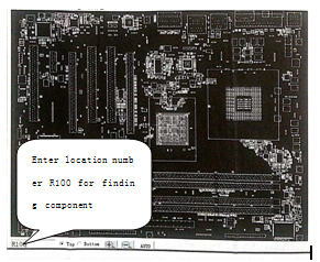
Fig.5 Component lookup bar
Step 2. Press the enter key to display the resistor R100 in the window, and the resistance color is orange. Click Resistor R100, and then click the resistor R100 to enlarge the position of the resistive RI00 clearly, as shown in figure 6.
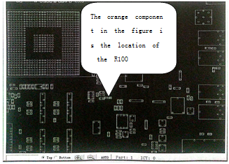
Fig.6 Component display position
If the component library is loaded and the mouse is placed over the corresponding component, the corresponding parameters of the component are displayed in the upper left or upper right corner at the same time (see figure 10).
5. Signal lookup method.
Step 1, right-click anywhere in the point bitmap to display the corresponding menu,
* step 2, select Net query to display the lookup box and enter the name of the lookup signal, as shown in figure 7.
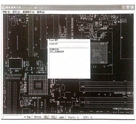
Fig.7 Signal lookup box
Step 3, click the relative signal name, and the window will display the components connected to the signal in orange color, and the blue one after magnification is the connecting point, as shown in figure 8.
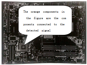
Fig.8 Signal connected component display diagram
6. Connection point lookup method.
Step 1, select the component pin and click to zoom in to see the component pin, then right-click the mouse over the component pin to display the shortcut menu.
Step 2, select "Show connected parts and PAD", where the orange connected components are shown, and the blue ones are connected points, as shown in figure 9.
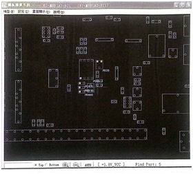
Fig.9 Component connection location diagram
This article is from Allicdata Electronics Limited

