How to measure motherboard standby conditions?
Standby condition is the prerequisite for the motherboard to power on. If standby conditions are not normal use of the South Bridge chip can not carry out the next action. Common standby conditions are VCCRTC. RTCRST#, 32.768kHz, 3VSB, RSMRST# (nVIDIA chipset motherboard also works with 25MHz crystal). Special machine condition measurement and maintenance methods are as follows.
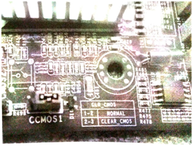
1. Plug in and measure whether the CMOS jumper cap voltage has 3V, and the motherboard jumper cap is shown in figure 1.

Figure 1 the CMOS jumper cap
(1)No 3V voltage, check if the dual diode VCCRTC is normal, the IO chip is short circuit, remove the jumper cap, and check the first pin voltage for 3V.
(2)With a 3V voltage, check that the RTCRST# of the South Bridge chip is short-circuited and that the capacitor is leakage.
2. To measure whether the 32.768kHz is normal or not, and the voltage of the crystal shaker can not be equal.
Common maintenance chip motherboard oscillator two-pin voltage difference is as follows.
Intel, AMD chipset: 0.1 -0.5V.
VIA chipset: 0.5-1V.
SIS chipset: 0. 5-1. 6V.
nVIDIA chipset: about 1-1. 6V (the nVIDIA motherboard also needs to measure a 25MHz crystal voltage of about 1.6 V).
(1)If the crystal shaker does not have a voltage, first measure whether the VCCRTC and RTCRST# are normal, and the well is normally delivered to the South Bridge chip. Then measure whether or not the crystal vibrator is short-circuit or broken from the ground to the ground. Then the resonant capacitor is removed, and finally the south bridge chip is replaced.
(2)If there is no voltage difference between the crystal legs, use the replacement method. First change the crystal oscillator, then change the resonant capacitance, resistance, and finally change the South Bridge chip.
(3)If the voltage difference between the crystal and the two pins is higher than the normal range, first change the capacitance, resistance, report, and then replant the South Bridge Chip, no longer replace the South Bridge Chip.
(4)If the hand touch crystal oscillator can power on, first change the crystal vibration, resonant capacitance, resistance, then replant the South Bridge chip, and finally replace the South Bridge Chip.
(5)The nVIDIA motherboard 25MIHz is not working, and if the standby voltage is normal, it is all a bridge problem.
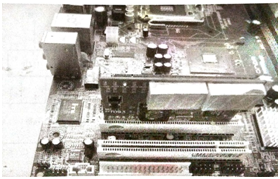
3. Check that the 3VSB standby power supply is working. Measure the A14 pin 4 of the PCI slot, or whether the visual diagnostic card standby light is lit, as shown in figure 2.

Figure 2 Diagnostic card standby light diagram.
4. Measure whether the RSMRST# is 3.3V voltage. Intel chipset, AMD chipset motherboard is called RSMRST#,nVIDIA chipset motherboard called PWRGD_SB.(most of the motherboard this signal is sent by the IO chip to the South Bridge chip, a small number of motherboards are directly pulled up by the resistance to standby power supply, unable to confirm the drawings or detach the South Bridge chip running line, you can also skip this step).
This article is from Allicdata Electronics Limited

