What is the basic RS trigger composed of NOR gates circuit?
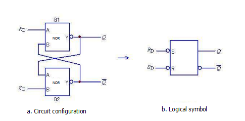
The basic RS flip-flop can also be constructed by two NOR gate cross coupling. The circuit structure and logical symbols are shown in Fig. 1.

Figure 1 shows the basic RS flip-flops with NOR gates.
RD and SD are reset (set to 0) and set (set to 1), respectively, which are different from the circuit of Figure 1, and they are all active high. There are also four combinations of signal inputs. When RD=0, SD=1, the flip-flop is set to 1; when RD=1, SD=0, the flip-flop is set to 0; when both are 1, the trigger state is undefined (is an illegal level); When RD=0, SD=0, the flip-flop remains unchanged.
Compared with the ordinary gate and the controlled gate circuit, the former input is a normal signal, the output state depends on the instant input; the latter input is a "transient" signal, there is a trigger characteristic, the output has a hold function, and the output is the input "past time" ", the output is maintained when the input condition is met. The input signal has constraints, so it limits its usefulness. The RS basic trigger is not actually used in IC devices. The actual application device is an IC product that has improved performance based on this, such as synchronous RS flip-flops, synchronous D flip-flops and other products.
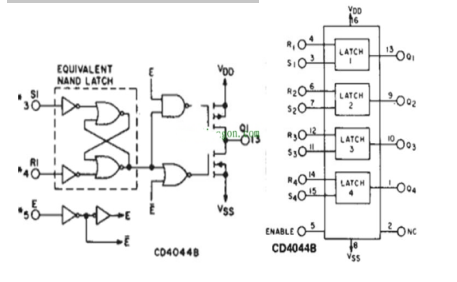
Circuit example: three-state R-S latch trigger CC4044B. The internal circuit structure and pin function are shown in the figure below.

Figure 2 CD4044B tri-state R-S latch
The basic R-S flip-flop is modified. If a transfer switch is added on the output side, an R-S flip-flop with a three-state transfer function can be obtained. It can be seen from its internal circuit structure that a) the controlled output stage is added, and the three-state output mode is used as EN. When the terminal is low, the output stage is high impedance (tri-state) with respect to the external circuit; b) the EN enable control terminal is added, the high level is the on state, the low level is the off state.
From the point of view of maintenance, the key point we need to pay attention to is how to determine the quality of the chip online and find alternative components (pin function, size).
Maintenance points:
a) In the high-impedance (transmission shutdown) state, the output level does not depend on the input signal, but is limited by the circuit designer (by adding the pull-up and pull-down resistors to define the static high and low levels);
b) In the normal transmission (EN terminal is high) state, with the basic R-S trigger operating characteristics: can be set to 0, can be set 1, output hold. The chip can be verified by verifying the three characteristics.
Unlike normal gates, the current output is "past tense" and is not a reflection of the immediate input signal. If you want to make sure the circuit is good or bad, you

