What are the output paths of main transformer of ATX power?
The number of pads (non-pins) on the circuit board side of the secondary windings of the common main transformer has a structure of "2-2-1". This is determined by the actual number of output paths of the main transformer.
The number of output paths of the main transformer refers to its physical output path (the number of secondary windings), and several outputs correspond to twice the number of windings. For most ATX power supplies, the ATX3.3V actually shares the same physical output (secondary winding) of the main transformer with the two low-voltage outputs of the ATX5V, plus the one-way physical output (secondary winding) corresponding to the ATX12V. The main transformer actually has two pairs (each pair) with a total of four secondary windings. The other end of the four secondary windings is joined together to become the ground of the low-voltage output side of the ATX power supply (this is the original starting point of the "output place" of the ATX power supply low-voltage side).
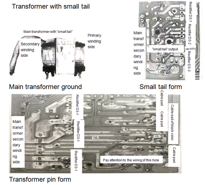
Some of the main transformer grounds appear in the form of a separate thick cable (like a small tail), as shown in Figure 2. The small tail corresponds to the largest one of the solder holes on the board and is easily distinguishable.
Some main transformers do not have a small tail, but also the ground is done on the bottom of the transformer (usually two pins, using the same wiring on the pad side). The benefits of this are obvious, it reduces the volume of the transformer is conducive to miniaturization of the overall volume of the power supply. In fact, in small-volume switching power supplies (such as laptop adapters), switching transformers of this construction are used.
Next, we calculate the number of pins that the main transformer's secondary winding-side should have.
(1) Secondary winding of ATX5V: 2 pins.
(2) Secondary winding of ATX12V: 2 pins.
(3) Ground obtained by connecting the other ends of the four windings in parallel: a small tail (denoted as 1) or 2 pins (corresponding to the same wiring on the pad side).
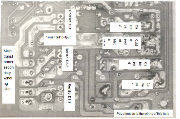
Correspondingly, there should also be 4 separate pads (numbered 1~4) and ground pads on the ATX power board pad. The ground shown in Fig. 3 appears in the form of a small tail (note the largest circular hole in the figure), and the ground shown in Fig. 4 is in the form of a transformer pin.

Let's look at a different power supply, as shown in Figure 5.

Figure 5 physical power supply.
The ATX power supply in figure 5 uses a main transformer with a "small tail", with a total of six pins rather than four common windings in its secondary windings. If you continue to look at the wiring of the six pins, they are connected to the negative poles of each of the three rectifier diodes.
This shows that the ATX3.3V output of this ATX power supply does not share a set of secondary windings with the output of the ATX5V and is a separate output. Moreover, there is only one "big bubble" in the power supply, and there are no two inductors in the magnetic amplifier regulator circuit corresponding to the ATX3.3V. Both facts unquestionably prove that its ATX3.3V is a stand-alone output.
This article is from Allicdata Electronics Limited. Reprinted need to indicate the source.

