| Allicdata Part #: | LTC6813HLWE-1#3ZZPBF-ND |
| Manufacturer Part#: |
LTC6813HLWE-1#3ZZPBF |
| Price: | $ 23.00 |
| Product Category: | Integrated Circuits (ICs) |
| Manufacturer: | Linear Technology/Analog Devices |
| Short Description: | 18 CHANNEL MULTICELL BATTERY STABattery Battery Mo... |
| More Detail: | N/A |
| DataSheet: |  LTC6813HLWE-1#3ZZPBF Datasheet/PDF LTC6813HLWE-1#3ZZPBF Datasheet/PDF |
| Quantity: | 8000 |
| Lead Free Status / RoHS Status: | RoHS Compliant |
| Moisture Sensitivity Level (MSL): | 3 (168 Hours) |
| 1 +: | $ 23.00000 |
| 10 +: | $ 22.31000 |
| 100 +: | $ 21.85000 |
| 1000 +: | $ 21.39000 |
| 10000 +: | $ 20.70000 |
| Series: | LTC6813 |
| Packaging: | Tray |
| Lead Free Status / RoHS Status: | -- |
| RoHS Status: | RoHS Compliant |
| Lead Free Status: | Lead Free |
| Part Status: | Active |
| Moisture Sensitivity Level (MSL): | -- |
| Function: | Battery Monitor |
| Battery Chemistry: | Multi-Chemistry |
| Number of Cells: | 18 |
| Fault Protection: | original new package LTC6813H |
| Interface: | SPI |
| Operating Temperature: | -40°C ~ 125°C |
| Package / Case: | 64-LQFP Exposed Pad |
| Supplier Device Package: | 64-LQFP-EP (10x10) |
| Base Part Number: | LTC6813 |
Due to market price fluctuations,if you need to purchase or consult the price.You can contact us or emial to us: sales@allicdata.com
1. DESCRIPTION
The LTC®6813-1 is a multicell battery stack monitor that measures up to 18 series connected battery cells with a total measurement error of less than 2.2mV. The cell measurement range of 0V to 5V makes the LTC6813HLWE-1#3ZZPBF suitable for most battery chemistries. All 18 cells can be measured in 290µs, and lower data acquisition rates can be selected for high noise reduction. Multiple LTC6813-1 devices can be connected in series, permitting simultaneous cell monitoring of long, high voltage battery strings. Each LTC6813-1 has an isoSPI interface for high speed, RF immune, long distance communications. Multiple devices are connected in a daisy chain with one host processor connection for all devices. This daisy chain can be operated bidirectionally, ensuring communication integrity, even in the event of a fault along the communication path. The LTC6813-1 can be powered directly from the battery stack or from an isolated supply. The LTC6813-1 includes passive balancing for each cell, with individual PWM duty cycle control for each cell. Other features include an onboard 5V regulator, nine general purpose I/O lines and a sleep mode, where current consumption is reduced to 6µA.

2. FEATURES
1. Measures Up to 18 Battery Cells in Series
2. 2.2mV Maximum Total Measurement Error
3. Stackable Architecture for High Voltage Systems
4. Built-In isoSPI™ Interface
- 1Mb Isolated Serial Communications
- Uses a Single Twisted Pair, Up to 100 Meters
- Low EMI Susceptibility and Emissions
- Bidirectional for Broken Wire Protection
5. 290µs to Measure All Cells in a System
6. Synchronized Voltage and Current Measurement
7. 16-Bit Delta-Sigma ADC with Programmable Noise Filter
8. Engineered for ISO 26262-Compliant Systems
9. Passive Cell Balancing Up to 200mA (Max) with Programmable Pulse-Width Modulation
10. 9 General Purpose Digital I/O or Analog Inputs
- Temperature or Other Sensor Inputs
- Configurable as an I2C or SPI Master
11. 6µA Sleep Mode Supply Current
12. 64-Lead eLQFP Package
13. AEC-Q100 Qualified for Automotive Applications
3. APPLICATIONS
1. Electric and Hybrid Electric Vehicles
2. Backup Battery Systems
3. Grid Energy Storage
4. High Power Portable Equipment
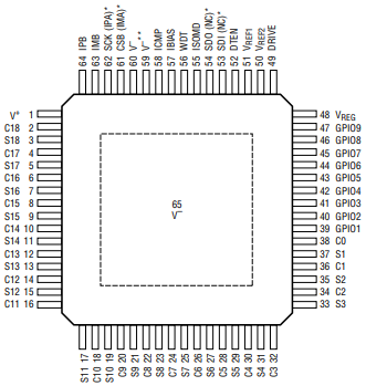
4. PIN CONFIGURATION

5. Application information
If the primary inductance is too low, The pulse amplitude will start to decrease and decay Pulse period. When the pulse drop is severe enough, The effective pulse width seen by the receiver will be greatly reduced, thereby reducing the noise margin. Some decline is acceptable as long as it is a relatively small percentage Total pulse amplitude. Leakage inductance is mainly Affect the rise and fall time of the pulse. Slowly rising And the fall time will effectively reduce the pulse width. pulse The width is determined by the receiver as the time of the signal It is higher than the threshold set by the ICMP pin. Rise slowly and The fall time cuts into the timing margin. Generally best Keep the pulse edge as fast as possible. When evaluating Transformers, it is also worth noting that parallel windings capacitance. Although the transformer has a very good CMRR At low frequencies, this suppression is reduced at high frequencies, mainly due to the capacitance between the windings. When choosing a transformer, it is best to choose A kind of parallel winding capacitance as little as possible. When choosing a transformer, it’s also important Choose a component with a sufficient isolation level application. Rated working voltage of transformer It is a key specification when selecting parts for the application. Interconnect daisy chain links between LTC6813-1 The device sees a stress of <90V in a typical application; ordinary Pulse and LAN type transformers are sufficient. connect For the LTC6820, a higher operating voltage rating may usually be required to obtain good long-term reliability. usually, Match the working voltage to the entire voltage The battery pack is conservative. Unfortunately, the transformer Suppliers usually only specify a one-second high-voltage test, This is not equal to the long-term ("permanent") rating of the part. For example, according to most security The standard 1.5kV rated transformer is expected to handle 230V continuously, while the 3kV equipment can 1100V long-term, although the manufacturer may not always Prove these levels. Generally, the higher voltage transformer is Known as "high insulation" or "reinforced insulation" type supplier. In most applications, common mode chokes are also needed to suppress noise.
6. PIN FUNCTIONS
1. C0 to C18: Cell Inputs.
2. S1 to S18: Balance Inputs/Outputs. 18 internal N-MOSFETs are connected between S(n) and C(n–1) for discharging cells.
3. V+: Positive Supply Pin.
4. V–: Negative Supply Pins. The V– pins must be shorted together, external to the IC.
5. VREF2: Buffered 2nd Reference Voltage for Driving Multiple 10k Thermistors. Bypass with an external 1μF capacitor.
6. VREF1: ADC Reference Voltage. Bypass with an external 1μF capacitor. No DC loads allowed.
7. GPIO[1:9]: General Purpose I/O. Can be used as digital inputs or digital outputs, or as analog inputs with a measurement range from V– to 5V. GPIO[3:5] can be used as an I2C or SPI port.
8. DTEN: Discharge Timer Enable. Connect this pin to VREG to enable the Discharge Timer.
9. DRIVE: Connect the base of an NPN to this pin. Connect the collector to V+ and the emitter to VREG.
10. VREG: 5V Regulator Input. Bypass with an external 1μF capacitor.
11. ISOMD: Serial Interface Mode. Connecting ISOMD to VREG configures pins 53, 54, 61 and 62 of the LTC6813-1 for 2-wire isolated interface (isoSPI) mode. Connecting ISOMD to V– configures the LTC6813-1 for 4-wire SPI mode.
12. WDT: Watchdog Timer Output Pin. This is an open drain NMOS digital output. It can be left unconnected or connected with a 1M resistor to VREG. If the LTC6813-1 does not receive a valid command within 2 seconds, the watchdog timer circuit will reset the LTC6813-1 and the WDT pin will go high impedance.
13. CSB, SCK, SDI, SDO: 4-Wire Serial Peripheral Interface (SPI). Active low chip select (CSB), serial clock (SCK) and serial data in (SDI) are digital inputs. Serial data out (SDO) is an open drain NMOS output pin. SDO requires a 5k pull-up resistor.
14. IPA, IMA: Isolated 2-Wire Serial Interface Port A.
- IPA (plus) and IMA (minus) are a differential input/output pair.
15. IPB, IMB: Isolated 2-Wire Serial Interface Port B.
- IPB (plus) and IMB (minus) are a differential input/output pair.
16. IBIAS: Isolated Interface Current Bias. Tie IBIAS to V– through a resistor divider to set the interface output current level. When the isoSPI interface is enabled, the IBIAS pin voltage is 2V. The IPA/IMA or IPB/IMB output current drive is set to 20 times the current, IB, sourced from the IBIAS pin.
17. ICMP: Isolated Interface Comparator Voltage Threshold Set. Tie this pin to the resistor divider between IBIAS and V– to set the voltage threshold of the isoSPI receiver comparators. The comparator thresholds are set to half the voltage on the ICMP pin.
18. Exposed Pad: V–. The Exposed Pad must be soldered to PCB.
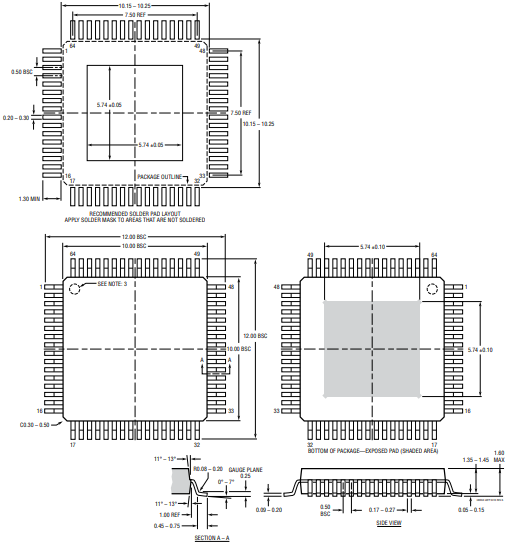
7. PACKAGE DESCRIPTION

Related products: LTC6813ILWE-1#3ZZPBF
| Part Number | Manufacturer | Price | Quantity | Description |
|---|
| LTC6994IDCB-1#TRPBF | Linear Techn... | 1.29 $ | 1000 | IC DELAY BLOCK 8TAP PROG ... |
| LTC6992HS6-2#TRPBF | Linear Techn... | 1.79 $ | 1000 | IC OSC SILICON PROG TSOT2... |
| LTC6957IDD-1#TRPBF | Linear Techn... | 3.16 $ | 1000 | IC CLK BUFFER DVR 1:2 12D... |
| LTC6263HMS#TRPBF | Linear Techn... | 2.62 $ | 1000 | IC OP AMP QUAD 30MHZ RRIO... |
| LTC6269HMS8E-10#TRPBF | Linear Techn... | 5.4 $ | 1000 | IC OPAMP 4GHZ SGL FET 8MS... |
| LTC6804IG-2#PBF | Linear Techn... | 13.22 $ | 3368 | IC MONITOR BATT STACK 48S... |
| LTC6084CMS8#TRPBF | Linear Techn... | 0.85 $ | 1000 | IC OPAMP GP 1.5MHZ RRO 8M... |
| LTC6088CGN#PBF | Linear Techn... | 1.99 $ | 622 | IC OPAMP GP 14MHZ RRO 16S... |
| LTC6262HMS8#PBF | Linear Techn... | 2.91 $ | 1000 | IC OP AMP DUAL 30MHZ RRIO... |
| LTC694CN8#PBF | Linear Techn... | 4.83 $ | 11 | IC MPU SUPERVISORY CIRCUI... |
| LTC6244HVCDD#TRPBF | Linear Techn... | 2.0 $ | 1000 | IC OPAMP GP 50MHZ RRO 8DF... |
| LTC6946IUFD-3 | Linear Techn... | 0.0 $ | 1000 | IC POWER MANAGEMENT |
| LTC6406CUD#PBF | Linear Techn... | 4.89 $ | 461 | IC DIFF AMP/DRIVER R-R 16... |
| LTC6101HVAHS5#TRMPBF | Linear Techn... | 1.98 $ | 500 | IC OPAMP CURR SENSE TSOT2... |
| LTC6101HVAIMS8#PBF | Linear Techn... | 2.99 $ | 187 | IC OPAMP CURR SENSE 200KH... |
| LTC692IS8#PBF | Linear Techn... | 5.24 $ | 100 | IC MPU SUPERVISORY CIRCUI... |
| LTC6652BHMS8-3.3#PBF | Linear Techn... | 2.35 $ | 1000 | IC VREF SERIES 3.3V 8MSOP... |
| LTC6752ISC6-1#TRPBF | Linear Techn... | 1.38 $ | 1000 | IC COMP R-R CMOS 280MHZ S... |
| LTC6262HDC#TRMPBF | Linear Techn... | 1.6 $ | 1000 | IC OP AMP DUAL 30MHZ RRIO... |
| LTC6090HS8E#TRPBF | Linear Techn... | 3.59 $ | 1000 | IC OPAMP GP 10MHZ RRO 8SO... |
| LTC6101CCS5#TRPBF | Linear Techn... | 0.91 $ | 1000 | IC OPAMP CURR SENSE TSOT2... |
| LTC6995IDCB-1#TRPBF | Linear Techn... | 1.36 $ | 1000 | IC OSC SILICON PROG 6-DFN... |
| LTC6905IS5#TRPBF | Linear Techn... | 1.63 $ | 1000 | IC OSC SILICON PROG TSOT2... |
| LTC6255IDC#TRPBF | Linear Techn... | 1.2 $ | 1000 | IC OPAMP GP 6.5MHZ RRO 6D... |
| LTC6912CDE-2#PBF | Linear Techn... | 1.92 $ | 1000 | IC OPAMP PGA 30MHZ RRO 12... |
| LTC6915CDE#TRPBF | Linear Techn... | 2.23 $ | 1000 | IC OPAMP INSTR 200KHZ RRO... |
| LTC6930IMS8-5.00#PBF | Linear Techn... | 2.28 $ | 18 | IC OSC SILICON 5MHZ 8-MSO... |
| LTC6992HS6-4#TRPBF | Linear Techn... | 1.79 $ | 1000 | IC OSC SILICON PROG TSOT2... |
| LTC6909IMS#TRPBF | Linear Techn... | 2.48 $ | 1000 | IC OSC SILICON PROG 16-MS... |
| LTC6957IDD-3#TRPBF | Linear Techn... | 3.16 $ | 1000 | IC CLK BUFFER DVR 1:2 12D... |
| LTC6262HTS8#TRMPBF | Linear Techn... | 1.6 $ | 1000 | IC OP AMP DUAL 30MHZ RRIO... |
| LTC6803HG-1#TRPBF | Linear Techn... | 9.22 $ | 1000 | IC MONITOR BATT STACK 44-... |
| LTC6652AHMS8-5#TRPBF | Linear Techn... | 2.84 $ | 1000 | IC VREF SERIES 5V 8MSOPSe... |
| LTC6947IUFD#TRPBF | Linear Techn... | 5.15 $ | 1000 | IC SYNTHESIZER FRACT-N PL... |
| LTC6930HDCB-5.00 | Linear Techn... | 0.0 $ | 1000 | IC POWER MANAGEMENTOscill... |
| LTC6930IDCB-8.00 | Linear Techn... | 0.0 $ | 1000 | IC POWER MANAGEMENTOscill... |
| LTC6946IUFD-4 | Linear Techn... | 0.0 $ | 1000 | IC POWER MANAGEMENT |
| LTC6905MPS5#TRMPBF | Linear Techn... | 4.15 $ | 500 | IC OSC SILICON PROG TSOT2... |
| LTC6991CDCB#TRMPBF | Linear Techn... | 1.11 $ | 500 | IC OSC SILICON PROG 6-DFN... |
| LTC6995CS6-2#TRPBF | Linear Techn... | 1.18 $ | 1000 | IC OSC SILICON PROG TSOT2... |
Battery Battery Monitor IC Multi-Chemist...

IC USB HOST ADAPTR EMULATOR TDFNBattery ...

IC BATTERY MONITOR LI+ FLIPCHIPBattery B...

IC SBS-COMPL GAS GAUGE 28QSOPBattery Bat...

IC PROTECT/MONITOR 4CELL 28TSSOPBattery ...

LITHIUM-ION BATT PROTECT 16-SOICBattery ...


