What are the applications of decoupling capacitors in single-chip circuits?
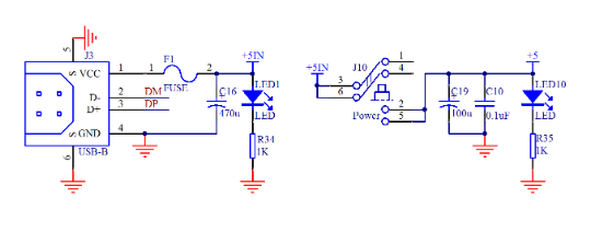
First look at Figure 1, which is the USB interface and power supply circuit.

Figure 1 USB interface and power supply circuit
On the left side, after passing the fuse, a capacitor 470uF of 470uF is connected. On the right side of the figure, after switching, a capacitor C19 of 100uF is connected, and a capacitor C10 of 0.1uF is connected in parallel. C16 and C19 play the same role. The role of C10 is different from the two. Let us introduce these two capacitors first.
A capacitor with a relatively large capacitance can theoretically be understood as a water tank. At the same time, the current can be directly understood as a water flow.
Function one, stability. Our complete set of circuits, the power level of the latter electronics is not the same, and the current required for the normal operation of the device is not static. For example, when there is a device in the latter stage that is still not working, the current consumption is 100mA, and suddenly the work is involved, the current is increased to 150mA. If there is no water tank at this time, the voltage (water level) in the circuit will drop suddenly, for example. The 5V voltage suddenly drops to 3V. Some electronic components in the system must be higher than a certain voltage to work properly. If the voltage is too low, it will not work directly. At this time, the water tank is indispensable. At this time, the capacitor will release the amount of electricity stored inside, stabilize the voltage, of course, then the current of the previous stage will fill the tank in time.
Function two, buffering effect. At the moment of power-on, when the current flows down from the power supply, it is unstable, and it is easy to impact the electronic device. Adding a capacitor can serve as a buffer. Just like our direct watering faucet, it is easy to break down flowers and plants. We only need to add a pool at the faucet, let the water pass through the pool and then slowly flow into the grass, it will not damage the flowers and plants, and play an effective protective role.
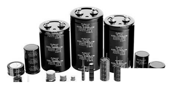
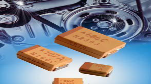
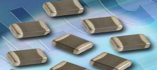
With this capacitor, it can be said that our voltage and current will be stable and will not cause large fluctuations. This type of capacitor is commonly used in three types as shown in Figure 2, Figure 3, and Figure 4:

Figure 2 Aluminum electrolytic capacitor

Figure 3 Tantalum Capacitor

Figure 4 Ceramic Capacitor
These three types of capacitors are the three most commonly used. The first one takes up a lot of space and the price is the cheapest. The second and third types are small, occupying a small space, and the performance is generally slightly better than the first one, but the price is also expensive. Of course, in addition to the price, there are some special parameters, and there are many considerations in the occasion of high communication requirements. Under the same qualified withstand voltage and capacitance, the first 470uF capacitor is less than a dime, while the second and third may cost about $1.
The choice of capacitance, the first parameter is the consideration of the withstand voltage value. We use a 5V system. The withstand voltage of the capacitor is higher than 5V. It is generally recommended to be 1.5 times to 2 times. In some cases, it can be slightly higher. We use 10V withstand voltage on our board. The second parameter is the capacitance value. This needs to be selected according to experience. When selecting, it depends on the power consumption of the whole system in which this capacitor works. If the system consumes a lot of power, the fluctuation may be large. The value should be chosen to be larger, and vice versa.
The students just started to design the circuit to imitate others and slowly accumulate. For example, when the current suddenly increases from 100mA to 150mA, even if this capacitor is added, the voltage will fluctuate slightly, such as from 5V to 4.9V, but as long as the device on our board is above 4.9V, it can work normally. In this case, this fluctuation is allowed, but if it is not added or added, the voltage fluctuation is relatively large, and some devices will work abnormally. However, if the addition is too large, it takes up space and the price is high, so the selection of this local capacitor is more reference experience.
Let us look at another capacitor C10 in Figure 1, which has a small capacitance of 0.1uF, or 100nF, to filter out high-frequency signal interference. Such as ESD, EFT, etc. We have learned the characteristics of capacitors at the beginning - we can pass AC and DC, but the parameters of the capacitors have different effects on the interference of different frequency segments. This 100nF capacitor is a value that our predecessors have based on the frequency of the interference, based on the parameters of the board, based on the parameters of the capacitor itself. That is to say, in the future, when designing the digital circuit, the decoupling high-frequency capacitor at the power supply can directly use this 0.1uF.
If you want to know more, our website has product specifications for the capacitors, you can go to ALLICDATA ELECTRONICS LIMITED to get more information

