What is a common-base amplifier circuit and Walmanization?
This article describes the characteristics of the common-base amplifier.
Three typical amplifying circuits of triodes, common shot, common set and common base have common characteristics. The combination of the cascode circuit solves the disadvantage of the output large impedance of the common shot circuit, but the bandwidth problem is not solved due to the "Miller effect". Here, it is necessary to introduce a common-base amplifying circuit.
1.Common-base amplifying circuit
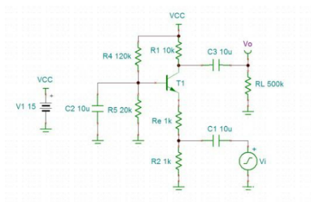
The circuit diagram of the common-base floating-point circuit is as follows. The input voltage enters the triode from the emitter, and the output voltage is the collector of the triode.
Magnification: A = Rc / Re, the same as the amplitude of the common-emitter amplifier circuit, but for forward amplification. Input impedance: Zin = Re || R2, since the input signal is not input from the base, there is no isolation effect of beta amplification, so the input impedance is small. Output impedance: Zout = Rc || RL, same as the common-amplifier circuit.

The biggest advantage of the common-base amplifier circuit is its bandwidth characteristics. As can be seen from the above circuit diagram, due to the large capacitance C2 of the base of the triode,The base and emitter are a constant diode with a constant tube drop of 0.7V. The emitter of the triode is also an AC base. Therefore, the parasitic capacitance Cbe of the triode does not have the effect of amplifying A times of the Miller effect, so the frequency characteristics are good.
The scanning frequency can obtain the above frequency response result, and it can be seen that the 3dB bandwidth of the common-base amplifying circuit can reach 4.8MHz.
2, Walmanization
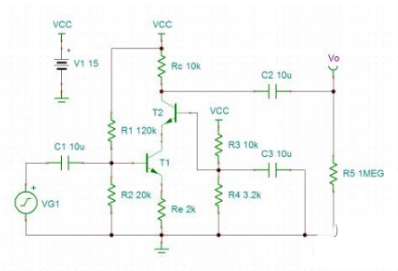
The bandwidth of the common-emitter amplifier circuit can be increased by cascading the common-base amplifier circuit. This ingenious method is called "Walmanization". The circuit diagram is as follows:

Cascade common base amplification circuit diagram
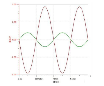
The simulation results are as follows:

Co-fired common-base amplifier circuit simulation results
Due to the introduction of T2, the collector of T1 is grounded, so the "Miller effect" caused by the parasitic capacitance Cbc of T1 does not exist, so that the frequency characteristics of the circuit are better.
3, Summary
1. The common-base amplifier circuit has a small input impedance and a large output impedance, which is a disadvantage.
2. The frequency characteristics of the common-base amplifier circuit are good.
3. The common-base amplifier circuit has the same amplification factor as the common-emitter amplifier circuit, but is positive amplification.
4. The common-base amplifier circuit and the common-emitter amplifier circuit can improve its frequency characteristics, which is called “Walmanization”.
If you want to know more, our website has product specifications for the common-base amplifier, you can go to ALLICDATA ELECTRONICS LIMITED to get more information

