Do you know the electronic filter mapping methods?
Electronic filter
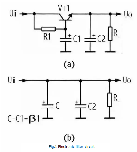
Figure 1 is the electronic filter. VT1 in the circuit is a triode that acts as a filter tube. C1 is the base filter capacitor of VT1, R1 is the base bias resistor of VT1, RL is the load of this filter circuit, and C2 is the filter capacitor of the output voltage.

The working principle of the electronic filter circuit is as follows:
1. VT1, R1, C1 in the circuit form an electronic filter circuit, this circuit is equivalent to a capacitor with a capacity of C1 × β1, β1 is the current amplification times of VT1, and the current amplification times of the transistor is large, so the power capacity is large, and the filtering performance of the electronic filter is good. The equivalent circuit is shown in Figure 1(b). In the figure, C is the equivalent capacitance.
2. In the electronic filter, the filtering is mainly realized by R1 and C1, which is also the RC filter circuit. The DC current flowing through the load in this circuit is the emitter current of VT1, and the current of the filter resistor R1 is the base current of VT1, and the base current is small, So the resistance of the filter resistor R1 can be set very large ( the filtering effect is good), but it does not cause the DC output voltage to drop a lot.
3.R1 and C1 in the circuit form an RC filter circuit. R1 provides the base bias current for VT1 and is also the filter resistor. Since the current flowing through R1 is the base bias current of VT1, this current is small, and the resistance of R1 can be made larger, so that the filtering effect of R1 and C1 is good. There is very little AC component in the DC voltage at the base of VT1. Since the emitter voltage has the characteristics of following the base voltage, the AC component of the VT1 emitter output voltage is also small, achieving the purpose of filtering.
4. The resistance value of R1 in the circuit determines the base current of VT1, which determines the tube voltage drop between the collector and emitter of VT1, which determines the DC voltage of the VT1 emitter output, so change R1. The size of the DC output voltage +V can be adjusted.
2. Electronically regulated filter

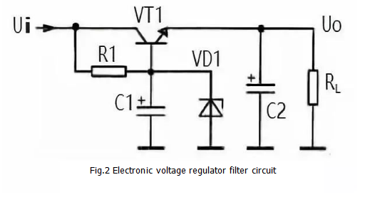
Figure 2 shows another electronically regulated filter, compared to the previous circuit a Zener diode VD1 connected between the base and ground of VT1. The principle of electronic voltage regulation is as follows:
After the Zener diode VD1 is connected between the base and ground of VT1, the input voltage is reverse biased by the voltage regulator diode VD1 via R1. At this time, the voltage regulation characteristic of VD1 stabilizes the base voltage of the VT1 tube. The DC voltage of the VT1 emitter output is also relatively stable. Note: The stability of this voltage is determined by the regulation characteristics of VD1 and has nothing to do with the electronic filter circuit itself.
R1 is also the current limiting protection resistor of VD1. After adding the Zener diode VD1, changing the size of R1 does not change the output voltage of the VT1 emitter. Since the VT1 has a PN junction voltage drop at the emitter junction, the emitter output voltage is slightly smaller than the regulated value of VD1.
C1, R1 and VT1 also form an electronic filter circuit for filtering.
In some cases, in order to further improve the filtering effect, a double-tube electronic filter circuit can be used, and two electronic filter tubes constitute a composite tube circuit. Thus, the total current amplification times is the product of the current amplification times of each tube, which obviously improves the filtering effect.
Power filter circuit diagram summary
The main points of attention regarding the analysis of the power supply filter circuit are as follows:
(1) When analyzing the working principle of the filter inductor, it is mainly recognized that the resistance of the inductor to the direct current is small, and there is no inductive reactance, but there is an inductive reactance to the alternating current.
(2) When performing electronic filter circuit analysis, it is necessary to know that the capacitance on the base of the electronic filter tube is a key component of the filter. In addition, to analyze the DC circuit, the electronic filter tube has a base current and a collector and emitter current. The current flowing through the load is the emitter current of the electronic filter tube. Changing the base current can adjust the tube voltage drop between the collector and the emitter of the electronic filter tube, thereby changing the DC voltage output of the electronic filter.
(3) When analyzing the working principle of the filter capacitor, it mainly uses the "isolated DC conduction and AC" characteristic of the capacitor, or the charging and discharging characteristics, that is, when the rectifier circuit outputs a unidirectional pulsating DC voltage, the filter capacitor is charged. When the pulsating DC voltage is output, the filter capacitor discharges the load.
(4) The electronic filter itself has no voltage regulation function, but the DC voltage of the output can be stabilized after the Zener diode is added.
If you want to know more, our website has product specifications for the electronic filter, you can go to ALLICDATA ELECTRONICS LIMITED to get more information

