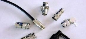
How will the high-power RF and microwave of RF connectors be affected?
Filter
Since the filter can be used as a band-selective attenuator or a reflector for out-of-band signals, it is necessary to consider the type of upstream electronic equipment and the signal entering the filter. The absorption filter will absorb RF energy from the out-of-band signal and convert it into heat. Among them, the reflection filter redirects the RF energy back to the source. This type of filter may damage sensitive upstream electronic equipment due to overpower or overvoltage. According to the filter technology and structure, the power handling capability of the filter is usually highly dependent on frequency.
As with most RF and microwave components, the power threshold of higher frequency components is lower than its low power components. The relative size and material of the filter will have a significant impact on power and frequency limitations. The passband of the filter naturally attenuates the signal slightly, so in terms of RF energy absorption or reflection, the passband characteristics are just as important as the out-of-band filter characteristics.
Directional coupler and power splitter / combiner
Directional couplers have many of the same concerns and constraints as adapters, adding complexity to built-in terminations or forward / reverse coupled signal paths. Moreover, the coupling signal path of the directional coupler is a few hundred, thousands, or tens of thousands of RF energy through the main propagation line. Because the power level on the coupling line is significantly reduced, even for high-power waveguide couplers, the coupling line is usually a coaxial connector. For hybrid couplers or 3dB 90 ° hybrid couplers, this is obviously not the case, they evenly distribute the power of the signal in two equal RF signal paths.

Generally, directional couplers are designed to have very low insertion loss and reflection. At high power levels, if not precisely designed, the coupling method will introduce significant insertion loss and reflection. Another factor to consider is the loading of the coupling line. Although at low power levels, simple termination may be sufficient. However, at higher power levels, any mismatch or reflection may cause a large amount of power to be fed into the main signal path. Moreover, depending on the coupling strength, the terminal of the directional coupler may require higher power processing than its low-power counterpart.
Much like a directional coupler, a power splitter separates RF signal energy along multiple paths. Among them, the power combiner feeds the RF signal energy into a main path. The problems of insertion loss and reflection are about the same as power splitter / combiner because they are the same as directional couplers. The main difference is that the power splitter / combiner is usually at approximately equal power levels, but not the phase. As a result of this, any impedance or VSWR mismatch in the connection or feeder may cause undesirable signal degradation, phase deviation and reflection. Some power splitters / combiners have inputs or outputs that are waveguide or coaxial connections, and the input and output use different connector sizes or technologies.
Passive intermodulation distortion in high-power passive devices
PIM has a significant impact on wireless network performance, especially on high-power radio frequency electronic equipment. Since PIM is often difficult to determine in a complete passive device system, if PIM is a design issue, having high accuracy and low PIM passive components may be the first step to ensure a lower PIM threshold. Any non-linearities in the material or environmentally induced non-linearities can lead to high levels of PIM.
Whether it is surface defects, microcracks or different material connections, high power levels usually exacerbate the nonlinear effects that lead to PIM. Since high-power applications are also often associated with more extreme environments, temperature changes, vibration, and material aging can also lead to non-linearities in PIM. To reduce the PIM response, each individual connection and component can be verified to operate with a reduced third-order intermodulation intercept point, thereby reducing distortion. Through rigorous post-assembly testing, the PIM response can also be confirmed after installation.
Thermal management challenges, lifetime and material degradation
High power levels at high frequencies tend to cause RF energy dissipation in non-ideal surfaces and materials. Dissipation of RF energy to most surfaces can cause heating. RF heating can cause material changes in peak power operation or material degradation over several cycles of use.
It is understandable that the temperature and RF power level specifications of the device should be kept within a reasonable range. Since many manufacturers are very optimistic about the performance of their products, there are reasons to allow as much power and heat margin as possible under other design constraints. This is especially important in critical applications that cannot tolerate downtime, because thermal stress can cause thermal runaway, resulting in rapid equipment failure.
Other environmental factors, such as moisture ingress and shock / vibration, can also temporarily reduce the power and heat treatment capabilities of the component. Thorough testing of high-power components in a salt spray, temperature, and mechanical stress test bench is often used to verify component design in extreme cases of certain applications.
If you want to know more, our website has product specifications for connectors, you can go to ALLICDATA ELECTRONICS LIMITED to get more information

