SATA hard disk interface circuit analysis and maintenance.
1. SATA interface introduction.
SATA is the abbreviation for Serial ATA. This is a new type of hard disk interface which is completely different from parallel ATA, which is named for serial data transmission. With embedded clock signal, SATA bus has stronger error correction capability. The biggest difference is that the transmission instructions (not only data) can be checked, and if errors are found, the reliability of data transmission can be greatly improved. The SATA interface also has a simple structure. The benefits of supporting hot-swappable. The SATA interface is shown in figure 1, and the pin definition is shown in Table 2.

Figure 1SATA interface physical. Table 2 SATA pin definitions.
2. The working principle of SATA interface.
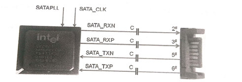
The connection of the SATA interface is shown in figure 2. The SATA RXN, SATA_RXP is the signal line of the hard disk data receiving and the SATA TXN,SATA_TXP is the signal line of the hard disk data output. After receiving SATAPLL power supply (1.5V) and SATA_CLK clock signal (100MHz), the internal SATA control module of south bridge chip exchanges data with hard disk through data receiving and output line.

Fig. 2 schematic diagram of the SATA interface.
3. SATA interface fault maintenance method.
1)Clear the CMOS settings first, then visually check if the interface is damaged, or if the South Bridge chip is missing.
2) Measured the capacitance of the SATA interface data line near the chip-end of the South Bridge to determine whether the data line is normal (the normal value is 200 ~ 300, and the red and black pen should be grounded once each time). If the value is small, the bridge is bad; the value is too large, there is a line break or bridge welding.
3)A universal meter is used to measure whether the coupling capacitor is normal or not, and the normal capacitance is about 10nF.
4)Check if the SATA controller clock signal of the South Bridge chip is normal. The SATA controller clock signal of the chip group is sent out by the clock chip, and the frequency is 100MHz. The SATA controller clock of the AMD chipset is provided by the 25MHz crystal oscillator next to the South Bridge chip.
5) Check if the precision resistor next to the South Bridge chip is normal.
6) If the above conditions are normal, the SATA interface can not be used, finally replace the South Bridge chip.

