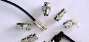
What are the factors affecting the high-power RF and microwave of RF connectors?
High levels of RF and microwave power are invisible, difficult to detect, and can generate incredible heat in a small area. Generally, overpower pressure can only be detected after a component failure or a complete system failure. This situation is often encountered in telecommunications and aerospace / defense applications, because the use and exposure of high power levels are necessary to meet the performance requirements of these applications.
High enough RF and microwave power levels can damage components in the signal path, which may be the result of poor design, material aging / fatigue, or even strategic electronic attacks. Any critical system that may encounter high-power RF and microwave energy must be carefully designed and supported by the components specified for the maximum potential power level. Other problems, such as RF leakage, passive intermodulation distortion, and harmonic distortion, are exacerbated at high power levels because the quality of components must be considered more.
Any interconnect or component with insertion loss may absorb enough RF and microwave energy to cause damage. This is why all RF and microwave components have maximum power ratings. Generally, because RF energy has several different operating modes, the rated power will be specified for continuous wave (CW) or pulsed power. In addition, because the various materials that make up an RF component can change the behavior of different power, temperature, voltage, current, and age, these parameters are often specified. As always, some manufacturers are more generous with the specified functions of their components, so it is recommended to test specific components under actual operating conditions to avoid field failures. This is a particular concern for RF and microwave components, as cascading failures are very common.
Coaxial or waveguide interconnect
Depending on frequency, power level and physical requirements, coaxial or waveguide interconnects are used for high-power RF and microwave applications. The size of these two technologies varies with frequency and requires higher precision materials and manufacturing to handle higher power levels. Generally, as a product of the way RF energy passes through a waveguide with an air dielectric, the waveguide tends to be able to handle higher power levels than comparable coaxial technologies. On the other hand, waveguides are usually more expensive than coaxial technology, custom installation and narrow-band solutions.
This means that for applications that require lower cost, more flexible installation, higher signal routing density, and medium power levels, coaxial technology may be the first choice. In addition, due to the reduction in cost and size, the choice of components that use coaxial interconnects on waveguide interconnects is greater. Although broadband and usually more straightforward installations, waveguide technology often exceeds coaxial in terms of high performance, ruggedness and reliability. Generally, these interconnection technologies are used in series, and where possible, the highest power and fidelity signals are routed through the waveguide interconnection.
An important feature to note in coaxial technology is that their power and voltage-dependent dielectric breakdown is much lower than that of waveguide interconnects of similar frequencies. If weight and cost are of high concern, this may be acceptable. However, the issues of material outgassing and material property changes at high temperatures and pressures may reduce the feasibility of coaxial technology in aerospace applications.

Since each adapter and terminal introduce unnecessary insertion loss and reflection, careful selection of the correct components can prevent unnecessary signal degradation and may have many forms of adapters and terminals for sensitive electronic equipment, usually coaxial or waveguide , For high power applications. In addition, the adapter may be more complicated because the size and type of either end of the adapter may be different. In addition, the adapter itself may introduce turns or bends.
The power and frequency range of the adapter must be carefully checked, especially if the adapter is a waveguide to coaxial conversion. Waveguides can only make the bandwidth of the frequency band transmit with high signal fidelity, in which the coaxial technology only has a cut-off frequency. However, different coaxial connector types also have different power and frequency capacities. If the adapter is a transition between two different coaxial connector types, frequency, power handling, PIM, insertion loss and other parameters will be affected.
The terminal bears the brunt of the potential extreme RF energy in the device. Generally, terminals for high-power applications will have heat-dissipating metal bodies and may force air thermal management. Terminal impedance matching and voltage standing wave ratio (VSWR) are absolutely critical, because unpredictable reflections can cause overpower and overvoltage conditions in upstream electronics. In the case of shunting a high-power amplifier (HPA) to a terminal that does not meet sufficient VSWR specifications, this may be dangerous because it may permanently damage the HPA.
Attenuator
Like the terminator, the attenuator is designed to dissipate RF energy within the body of the device without generating any unwanted signal distortion or reflection. There are fixed and variable attenuators. For most extremely high power applications, fixed attenuators are more common. Like terminators, they can be waveguide or coaxial. In addition, the attenuator can also be an adapter of different size coaxial connector size, although this is rarely done with a waveguide connector.
A waveguide directional coupler may have a coaxial output because the power level of the coupled signal is low enough to be transmitted in a coaxial transmission line of lower weight and cost.
Depending on the amount of power dissipated in the attenuator design, metal radiators usually surround the body, and even forced cooling is an option. The higher the frequency, power handling and attenuation, the RF energy will be converted into heat. When installing the attenuator, it is important to ensure that the attenuator is adequately ventilated and not installed close to other heat-dissipating electronic equipment.
If you want to know more, our website has product specifications for connectors, you can go to ALLICDATA ELECTRONICS LIMITED to get more information

