How is the EMC of the isolation transformer designed?
Traditional transformer EMC design
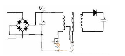
In addition to the MOSFET field-to-ground coupling, the noise voltage of the d-pole of the switching transistor couples the noise current to the loop where the secondary winding of the transformer is located through the parasitic capacitance of the transformer, and the coupling of the parasitic capacitance of the secondary loop to ground to ground is also the path of common mode current generation. Therefore, trying to reduce the common mode current flowing from the main winding of the transformer to the secondary winding is an effective EMC design method. The traditional transformer EMC design method is to add an isolation layer between the two windings, as shown in Figure 1.

Figure 1. Effect of transformer isolation layer on noise current
The design of the metal isolation layer directly connected to the ground line increases the common mode noise current and deteriorates the EMC performance. The isolation layer should be a node with stable potential in the circuit. Such a connection can effectively shunt the common mode current that originally flowed to the earth, thereby greatly reducing the level of conducted noise emission of the power line.
Node phase balance method
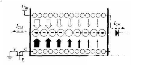
In the circuit, the active node of the noise voltage is not singular. Take the circuit analyzed in this paper as an example: In addition to the d pole of the power switch tube, the other end of the transformer front winding Uin is also a noise voltage active node, and the direction of the node voltage changes opposite to the d pole voltage of the field tube. Therefore, both ends of the secondary winding of the transformer are active nodes of opposite phase noise voltages. Figure 2 shows the distribution of the coils on the transformer skeleton after the node phase balance method.

Figure 2. Coupling of noise current inside the transformer
The innermost layer of the transformer bobbin is half of the coil of the pre-stage winding and connected to the d pole of the power switch tube; the coil of the middle layer is the secondary winding; the outermost layer is the other half of the pre-stage winding, which is connected to the node Uin. Since the noise current mainly passes through the parasitic capacitance coupling between the coil layers of the front and rear stages, the noise active nodes whose opposite directions of the front and rear coils are wound in pairs around the inner and outer layers can cancel most of the noise currents, greatly reducing The strength of the noise current that is ultimately coupled to the secondary.
The circuits discussed in this paper also have auxiliary power supplies for the pre-stage and secondary circuits, which are also powered by separate coils wound around the transformer. The presence of these two auxiliary coils provides an additional path for the propagation of noise currents. The auxiliary coil is designed to control the power supply of the circuit. Although the power of the control circuits themselves is small, their presence increases the parasitic capacitance of the circuit to ground, thereby sharing a portion of the work of coupling common mode noise from the active node to ground. However, sandwiching these windings between the windings of the preceding and secondary windings increases the distance between the windings of the front and rear windings, so that their interlayer parasitic capacitance is reduced and the noise current is reduced accordingly.
If you want to know more, our website has product specifications for transformer, you can go to ALLICDATA ELECTRONICS LIMITED to get more information

