What is the logic gate circuit of digital electronic technology?
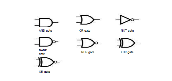
In the digital circuit design, the logic gate is the most basic arithmetic unit, and the AND gate, OR gate and NOT gate are the most basic logic gate units, but the logic used in the actual design is often much more complicated than, but They can all be implemented using a combination of AND, OR, and NOT. For example, NAND, NOR, XOR, and OR gate. The graphical symbols of these logic gates are as follows:

How to build a circuit utilizing a door unit?
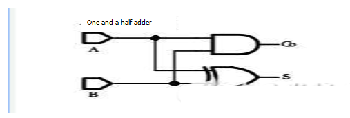
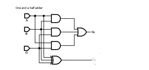
The circuit built by the gate unit is called the gate circuit. According to a certain logic relationship, different gate units are connected to realize the logic function we need. This is the purpose of digital circuit design. Here are two examples of using a logic gate unit to build a half adder and a full adder gate circuit:

The figure above is a half-adder circuit constructed by an AND gate and an XOR gate, where A and B are the input signals of the half adder, S is the result output of the half adder, C is the carry input of the half adder.

The above figure is a full adder circuit built by the logic gate unit. A and B are the input signals of the full adder, Ci is the carry input signal of the full adder, S is the full adder result output, and Co is the carry output of the full adder.
Why can I implement the addition function? The following is a simple analysis of the principle of the addition function of the above two gate circuits. First, explain the difference between the half adder and the full adder: the half adder only adds the input signals A and B regardless of the carry; the full adder adds the carry Ci in addition to the A and B additions.
Among them, the half adders are added, and only when A and B are both 1, the addition will generate a carry, so Co=A&B. When both A and B are 0, the addition result S=0. Only one of A and B is 0 and the other is 1, the addition result S=1, so S=A^B.
The operation of the full adder is a bit more complicated. When one or three of the three inputs A, B, and Ci are 1, the addition result S=1, otherwise S=0, so S=A^B^Ci; When any two or three of the three inputs A, B, and Ci are 1, the addition will result in a carry of Co = 1, otherwise Co = 0, so Co = A & B | A & C | B & C.
If you want to know more, our website has product specifications for logic gate circuit, you can go to ALLICDATA ELECTRONICS LIMITED to get more information

