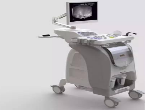
What are the electromagnetic compatibility problems often encontered in medical equipment?
1. The emission problem of switching power supply
The electromagnetic emission problem of switching power supplies or AC / DC converters has a long history. The circuit configuration of the switching power supply and the layout and structure of the switching power supply itself often make the electromagnetic emission of the switching power supply a big problem in its popularization and application. Although this problem is very common, it is particularly important in medical electronics. Therefore, where the volume and quality of medical equipment are not a problem, you can consider using a traditional linear regulated power supply. For the power supply part, volume and quality become the key factors of quality performance, so how to choose a switching power supply with excellent electromagnetic compatibility performance has become an important link in the design of the medical device.
2. Electromagnetic emission problem of liquid crystal display
With the development of computing technology, more and more cases are controlled by single-chip microcomputers in medical equipment, and the use of liquid crystal displays on the panel of the device as a human-machine dialogue interface is also increasing. The application of liquid crystal has also brought Liquid crystal display electromagnetic emission problems.
The liquid crystal display is usually driven by a cable drawn from the circuit board. Due to the high impedance of the liquid crystal display, the signal current sent to the liquid crystal display cannot be completely returned to the cable, and a small part of it will form Electromagnetic radiation enters the surrounding electromagnetic environment.
In order to suppress the electromagnetic emission problem of the liquid crystal display, it is first necessary to return the signal current to the driving circuit board with the shortest possible loop. A better method is to reduce the impedance in the return path of the signal current by setting a grounding plate under the cable. In addition, as a part of the structure of the liquid crystal display, the four corners of a metal case should be grounded on the back of the liquid crystal display.

3. Inter-coupling of internal circuits of the equipment
In the high-frequency state, there will be a problem of mutual coupling between the internal circuits of the device, so the layout of the circuit is improper, especially for the patient detection signal input circuit. Direct cause of the result.
When dealing with problems in the electromagnetic compatibility of equipment, inductors or ferrite cores are often placed between the input and output of the line to suppress radio frequency interference inside and outside the equipment, so that the The inductor at the end of the noise source carries a considerable high-frequency voltage. This high-frequency voltage can act on nearby metallic materials through capacitive coupling, such as ground layers, circuit boards, heat sinks, etc. Therefore, you must be very careful when using this interference suppression scheme to avoid coupling with some sensitive devices or sensitive circuits.
In addition, when the ferrite core is used to absorb the interference on the line, the effect of placing the core on the outside of the connection line is more obvious than placing it on the circuit board. Because this way can avoid the problem of coupling between the connecting line behind the magnetic core and the sensitive line.
If you want to know more, our website has product specifications for electromagnetic compatibility, you can go to ALLICDATA ELECTRONICS LIMITED to get more information

