What are the methods and techniques for detecting switching circuit?
The characteristic of the switching circuit is that it works in the state of cut-off-amplification, amplification-saturation, cut-off-saturation.
Their DC voltage and DC current vary with the presence or absence of the signal, that is, the DC voltage and DC current are different between the signal and the no signal.
These circuits are non-linear and generate a DC component when the signal passes. It is this new DC component that changes the original operating state and thus enters a new operating state. The static dynamic voltage difference we measured also reflects this fact.
Based on this voltage change, it is estimated whether the signal enters the circuit under test.
Since the multimeter's AC voltage file has low sensitivity and low internal resistance, the AC file can only be used to test the output voltage of some parts with certain output capability.
The sinusoidal AC voltage can be directly tested with the multimeter AC. The voltage in the general circuit often contains the pulsating component, that is, AC and DC exist at the same time. In this case, must cut off the DC and test his AC voltage. The specific method is to connect a capacitor in series with the multimeter's AC file.
For some circuits, it is sometimes necessary to test the current of the circuit to determine if the circuit is working properly. When testing the DC current, the circuit can be disconnected from the ammeter, or the value of the relevant voltage resistance in the circuit can be measured without cutting off the circuit to calculate the current value.

Knowing the working state of the circuit, in order to identify whether the circuit is in this state, it is necessary to grasp the method of judging the working state according to the voltage value. The operating state of the transistor is determined by the biasing direction of the emitter junction and the collector junction, and the bias direction can be judged by measuring the voltage of the three pins.
It should be noted that the above determination method is not suitable for the circuit in which the oscillation circuit and the BE junction are reverse biased. Because their reverse bias voltage is the signal generated by the BE junction itself, not added.
The bias state of the oscillator emitter junction is generally insufficient forward bias and reverse biased state. If the BE junction voltage reaches the normal bias voltage, it stops oscillating.
Because there is a certain resistance between the power supply and the collector, the collector voltage will change as the collector current changes.
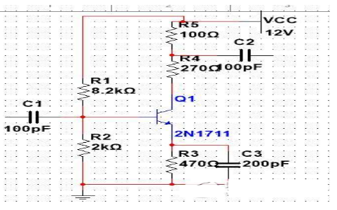
Therefore, after changing the bias state, observing the change of the collector voltage can introduce the change of the current, and further judge whether the transistor has the amplification capability. This kind of amplifying circuit does not change its working point regardless of the presence or absence of a signal, so this method is feasible. The method is to short the BE junction of the tube to be tested and should appear: UBE=0V, IB=0, IC=0. UCE=VCC. UE0.

That is, the transistor is like an open circuit. However, this method cannot be used for direct coupling circuits because it can cause the circuit to malfunction. For this kind of circuit, when there is no signal, it is saturated, and it is also possible to observe the change of UC by using the short-circuit BE junction.
A transistor operating in this state is already off when there is no signal. Only the external bias current can change the state. The method is to connect a resistor between the base of the tube to be tested and the power supply or ground to make it positively biased. The resistance can be 5 to 10 kohms.
If you want to know more, our website has product specifications for the switch, you can go to ALLICDATA ELECTRONICS LIMITED to get more information

