What is a differential signal, why use amplifier circuit ?
The two chips need to communicate. We connect them with one wire. One transmits 1, the other accepts 1, one transmits 0, and the other accepts 0. Isn't it good?
Because of interference, various kinds of interference, such as temperature, electromagnetic radiation, etc., these interferences make the transmission 1 no longer ideal 1, and the transmitted 0 is no longer ideal 0, but almost all of these interferences The common feature is that its interference with this wire is the same as its interference with the wire near this wire.
Using this feature, we use two wires to transmit the signal, one wire transmits the signal 1010 we want to transmit, and the other wire transmits the signal 0101 opposite to it. At the receiving end, we treat the two signals as bad, then we receive To the signal of 1 -1 1 -1, the signal we want to transmit can be recovered by level shifting or other means. The interference was eliminated during the process of doing the difference.

2, the basic structure of the differential amplifier circuit
The characteristics of all electronic components are affected by temperature, and semiconductor materials are most affected. For the PN junction, the temperature coefficient is -2.5mV/°C, which means that for every 1°C increase in temperature, the tube voltage drop of the diode or triode will be reduced by 2.5mV. It is conceivable that when the temperature is high to a certain extent, the diode The characteristics of the forward-to-back reverse cut-off do not exist, and all semiconductors do not work properly.
In the common-emitter amplifier circuit, the circuit base: the design of the Lec16-common-amplifier circuit, the temperature change will produce the voltage change ΔUbe between the base and emitter of the triode, and this phenomenon becomes "warm drift".
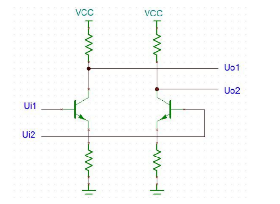
Using the idea of differential signals, we can solve the problem of temperature drift by establishing the above circuit diagram, input (Ui1-Ui2), and output (Uo1-Uo2). Temperature drift interference is eliminated during the process of doing poor.
3. Long tail differential circuit
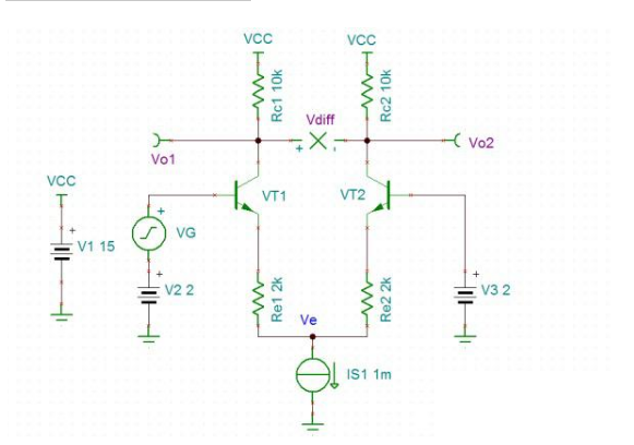
A more practical design is to use a long tail differential circuit, as shown in the figure, this circuit can be amazing, it can

Single-ended input, single-ended output, the amplification factor is 1/2 times that of the common common-amplifier circuit. Single-ended input, differential output, and amplification factor is 1 times that of ordinary common-emitter amplifier circuit. Differential input, single-ended output, amplification is 1 of the common common-amplifier circuit. Differential input, differential output, and amplification are 2 of the common common-amplifier circuit. This circuit is powerful because ΔUbe is generated when the temperature changes, but it compensates ΔUbe by introducing a constant current source, so that the voltage across Re remains unchanged, so that the current flowing through Re does not change. The current flowing through Rc is derived unchanged, and the Vo of the final output is unchanged.
Where ui represents the input signal and ube represents the voltage difference between the base and collector of the triode, which is a function of temperature. Now we only consider temperature drift, ui remains unchanged. Just look at the effect of temperature changes on the output. Deriving the two ends of this equation yields the following equation, which indicates that the ΔUbe caused by the temperature drift is compensated by ΔVe.
The simulation results of the long tail differential circuit are as follows. It can be seen from the results that when the single-ended signal is input, the amplification factor of the single-ended output is 1/2 of that of the ordinary common-emitter amplifier circuit. Magnification can be derived using the formula 1 for Ui.
If you want to know more, our website has product specifications for the amplifier, you can go to ALLICDATA ELECTRONICS LIMITED to get more information

