How to use the spread spectrum clock generator to reduce electromagnetic interference EMI?
Electromagnetic interference (EMI) is an energy that can affect the performance of an electrical/electronic device by causing an unexpected response or full operational effectiveness.
EMI is generated by radiated electromagnetic fields or induced voltages and currents. High clock frequencies and short edge rates in current high speed digital systems can also cause EMI problems.
An important source of conduction and emission EMI is electrical equipment that connects AC power lines, such as computers and switching power supplies, as well as electrical equipment with electric motors, such as refrigerators, air conditioners, and motorcycles.
Once the EMI of the electrical device is conducted into a circuit, the cable inside will “broadcast” the conducted EMI into the entire circuit in the form of RFI (radio interference) like an antenna.
EMI may have less impact and may cause catastrophic failure, so effective control of EMI is very important. Electromagnetic compatibility (EMC) refers to the ability of a system to operate in a specified environment without transmitting or transmitting excessive battery interference.

EMI standards and related costs
The purpose of the EMC standard is to ensure that electronic equipment does not affect the operation of other electronic equipment or even cause equipment failure.
The requirements for EMI shielding for consumer electronics devices such as "TV, radio, portable entertainment devices, video games and Internet devices" vary.
So far, various organizations have issued EMI specifications. In the United States, the FCC has released Part 15 J specification for Class A and Class B electronic equipment. Class A and Class A specifications are for industrial equipment, while Class B and B specifications are for consumer electronics. EMI rules reduce interference between electronic devices and address health and safety issues.
How to control EMI generally consider the following factors:
1) PCB design - "Isolation of sensitive components, power supplies and ground layers"
2) Circuit current - "EMI radiation will increase with increasing current"
3) Shielding/Filtering - "Combining reasonable design, filtration, shielding and other techniques to control EMI to the required level at the lowest cost"
4) Frequency, including slew rate - "EMI radiation causes an increase in frequency"
5) Bandwidth
6) Jitter the center frequency of the clock in the application system to spread the radiant energy into multiple frequency bands instead of letting all energy radiate to one frequency.
7) Circuit loop area - "Keep in minimum"
8) Spread spectrum clock - "appropriate spread frequency and modulation frequency"
Control and reduce EMI methods
There are two basic ways to control and reduce EMI: inhibition and absorption. The most common methods of noise reduction include proper device circuit design, shielding, grounding, filtering, isolation, separation and orientation, circuit impedance level control, cable design, and noise cancellation.
These methods require the use of passive and active components such as filters, chokes, ferrite beads, foils, and in conjunction with PCB design rules and Spread Spectrum Clock Generator (SSCG).
Solve EMI problems at the source
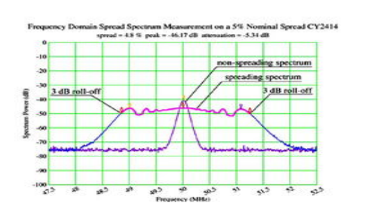
A fundamental principle of EMC design is to reduce EMI at the source of the PCB. The spread spectrum method is intended to extend the radiant energy generated in a particular bandwidth to the frequency domain to produce a signal with a larger bandwidth. The Exhibit Clock Generator (SSCG) can perform this function.
When choosing a spread spectrum clock to reduce EMI in consumer electronics, developers must ensure the following:
1) The system must pass the EMI type test. A good frequency profile and modulation frequency are the most important. The high-quality Hershey Kiss frequency profile is the best at reducing EMI; in contrast, the triangular frequency profile requires a larger amount of expansion to reduce EMI to the same level . The higher the modulation frequency, the lower the EMI.
2) Maintain system performance even if the spread spectrum has side effects. First, the PLL must operate in an ideal state, such as higher PFD and VCO frequencies and appropriate bandwidth. Second, the amount of frequency spread must be as small as possible to maintain high system timing margin and low inter-cycle jitter. With a smaller amount of frequency expansion, the average frequency of the system will not be reduced too much, so the system will not run as slow.
3) Minimize the impact on the total cost of the system. In consumer electronics, the price of spread spectrum clock chips has always been a major price issue. However, while consumer electronics is becoming more complex in recent years, developers must carefully consider development costs and risks.
For example, even if only one requirement is not met in suppressing EMI and jitter, the system clock of consumer electronics needs to be more likely to be adjusted. The flexibility of the programmable EMI suppression method can significantly reduce development costs and risks, ensuring that all requirements are met.
If you want to know more, our website has product specifications for the clock generator, you can go to ALLICDATA ELECTRONICS LIMITED to get more information

