What is the structure of the switching power supply transistor amplifier circuit?
An electronic circuit that increases the amplitude or power of an electrical signal. A device that uses an amplifying circuit to achieve amplification is called an amplifier. Its core is electronic active devices such as tubes and transistors. In order to achieve amplification, the amplifier must be powered. The commonly used energy source is a DC power source, but some amplifiers also use a high frequency power source as a pump source. The essence of the amplification is to transfer the energy of the power supply to the output signal. The purpose of the input signal is to control this transition so that the change in the output signal of the amplifier repeats or reflects the change in the input signal. In modern electronic systems, the generation, transmission, reception, transformation, and processing of electrical signals are almost always based on amplifier circuits.
For transistor amplifying circuits, we should first understand the characteristics of the circuit and the basic workflow. Familiar with the specific circuit to familiarize with the structural composition of each circuit. Then, according to the functions and functional characteristics of various key components in the circuit, the overall circuit type is divided. Finally, through the analysis of the circuit unit, the process of identifying the transistor amplifying circuit is completed.
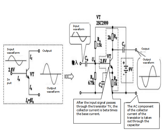
One of the most basic functions of a transistor is amplification, and therefore, a circuit made using a transistor has an amplification effect. When the input signal is applied to the base of the transistor, the base current IB changes, which in turn causes a corresponding change in the collector current IC. Since the transistor itself has a magnification factor β, according to the amplification relationship of the current IC=β×IB, the signal after passing through the transistor is amplified by β times, and the output signal is blocked by the coupling capacitor Cc, and then outputted at the output end of the circuit. The amplified signal waveform is obtained.

As can be seen from the figure, the waveform of the base input of the transistor is amplified by β times in the transistor, and the amplifying circuit made by using the technology is widely used in electronic products such as color televisions, DVD players, electromagnetic cookers, and mobile phones.
It is well known that a transistor has a current amplification function, the base current is the smallest, and is much smaller than the current of the other two pins, the emitter current is the largest (equal to the sum of the collector current and the base current), and the collector current and the base The ratio of the pole current is the amplification factor of the transistor.
The structure of the transistor amplifying circuit
The transistor amplifying circuit is mainly composed of a transistor, a resistor, a capacitor, and the like.
The resistors RA and RB have a voltage dividing function, and the power is supplied to the base of the transistor through the power source; the resistor RC supplies power to the collector through the power source; and the capacitors CB and CC mainly function to couple the AC and DC.
The core device in the transistor amplifying circuit is a transistor. According to its structure, the transistor can be divided into two major categories: NPN and PNP. The transistor is mainly composed of three regions, namely an emitter region, a base region and a collector region, and the lead lines of the three regions are respectively called an emitter (C), a base (B) and a collector (E). The PN junction between the emitter region and the base region is called an emitter junction, and the PN junction between the base region and the collector region is called a collector junction.
If you want to know more, our website has product specifications for the transistor amplifier, you can go to ALLICDATA ELECTRONICS LIMITED to get more information

