What is the working principle of crystal triode amplifier circuit?
The transistor can be seen as two PN junctions.
For NPN transistor: to turn on, two PN junctions are required to be in positive bias voltage. NPN uses B-E current (IB) to control C-E current (IC). The E potential is the lowest, and the C potential is usually the highest in normal amplification, that is, VC > VB > VE. Therefore, the current flow is from the C pole to the E pole. The B pole is the control foot, and the current of B flows to E.
For PNP transistors: PNP uses E-B current (IB) to control E-C current (IC). The E-pole potential is the highest, and the C-pole potential is usually the lowest in normal amplification, that is, VC < VB < VE. Therefore, the flow direction of current is from E-pole to C-pole. The B pole is the control foot, and the current of E flows to B.
Integrated Operational Amplifier: A direct coupled multistage amplifier with high voltage gain is made by integrated circuit technology. The circuit is divided into four parts: input stage, intermediate stage, output stage and bias circuit. Simply put, the integrated operational amplifier is a module. It consists of pipes, resistors, capacitors, etc. It has high open-loop voltage amplification factor.
A triode is a device. It has the function of current amplification and realizes voltage amplification by utilizing the ability of current amplification. That is to say, the integrated operational amplifier contains a transistor. Now you know, they are very different in structure. The integrated operational amplifier has small drift, high reliability, high voltage and high speed. But now operational amplifiers are commonly used to amplify signals. Triodes are very unstable and easily affected by temperature, so they are generally used as switches.
Amplification circuit is the most basic and common electronic circuit composed of crystal triode. The function of amplifying circuit is to amplify and output weak audio signal and to promote the sound of loudspeaker. Amplifier circuit is composed of basic crystal triode, capacitor, resistance and DC power supply. We know that the microphone, MP3, mobile phone and other audio signals are weak, which are connected to the speaker after various amplification circuits. Audio signal is an AC signal (AC voltage).

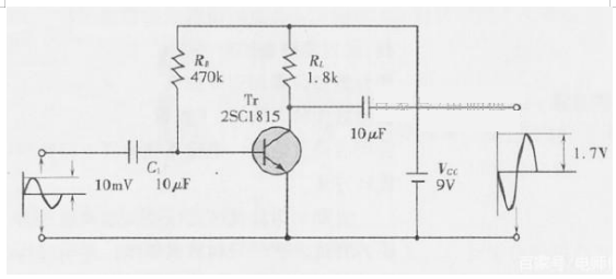
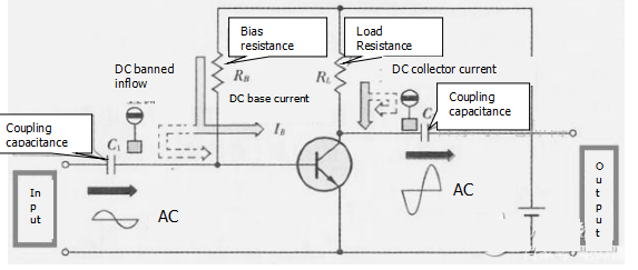
C1, C2 capacitors: AC coupling capacitors. The basic function of capacitors is to isolate DC from AC. Therefore, audio AC signals can pass smoothly. They are important components connecting audio signals with crystal transistors and can block the passage of DC signals. Electronic component parameters: 10UF/50V.
RB Resistance: Bias Resistance, which determines the base current IB of a crystal transistor. Electronic component parameters: 470K 1/4W. RL Resistor: Load Resistor is the key component to obtain the output voltage. Electronic component parameters: 1.8K 1/4W. Crystal triode: It is a core amplifier. It can use NPN type crystal triodes such as 1815, 8050, 9014, etc. DC power supply: DC9V.

The amplifier circuit above is a common emitter amplifier circuit. The audio signal is input by the base and emitter of the crystal transistor, and output from the collector and emitter. The emitter pole is grounded and the emitter pole is shared, so it is called common emitter amplifier circuit. Characteristic of common emitter amplifier circuit: 1. It has large current and voltage gain. 2. The waveforms of input and output audio signals are just the opposite (the input and output waveforms in the figure above can be seen intuitively).
If you want to know more, our website has product specifications for the crystal triode amplifier, you can go to ALLICDATA ELECTRONICS LIMITED to get more information

