How should the magnification of the triode amplifier circuit be calculated?
Friends who have studied the model electricity should be familiar with the amplifier circuit of the triode or FET. This is the key point in the mode, and it is also difficult. This time, taking the three configurations of the triode amplifier circuit as an example, let us briefly explain the calculation formula of the amplification factor of the amplifier circuit.
The basic configuration amplifying circuit composed of triodes can be divided into three types, namely, a common-emitter amplifying circuit, a common-base amplifying circuit and a common-collecting amplifying circuit.
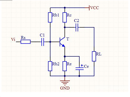
The common-emitter amplifying circuit is a commonly used one in low-frequency circuits. In the case of writing formulas, some books are divided into emitters plus resistors and no resistors. In fact, they can also be combined, because if the emitter does not add resistance, it can be completely Think that the resistance on the emitter is zero, first look at the schematic diagram of the common-emitter amplifier circuit.

It seems complicated, but the analysis can be divided into two steps, one is the analysis of the AC circuit, the other is the analysis of the DC circuit, the DC circuit is generally used to find the static working point, because there is a time to find the magnification The parameters are related to the selection of the static working point. As we will mention later, we want to know magnified multiple, so the AC path should be used.
For the above actual circuit communication analysis is not very conducive to understanding, here is the following circuit as an example.

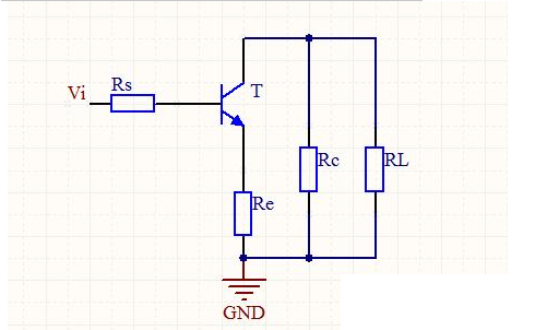
This circuit looks very simple, where T is a triode, Rs is the internal resistance of the signal source, Re is the resistance on the emitter, R c is the resistance on the collector, RL is the load, draw the AC path (that is That picture), if you want to derive the formula yourself, you can change the triode in the AC path to the small signal equivalent circuit of the triode. The corresponding positions of the other components do not need to be moved, so the derivation is not given here, and the result is directly given.
Where β is the triode magnified multiple, R L′ is the equivalent resistance of R c in parallel with RL, Re is the resistance on the emitter, and R b b′ is composed of the base lead resistance and the base resistance, the value About tens of ohms, R b b' and the triode itself are independent of the external circuit, R b'e resistance is very large, at the kilo-ohm level, so R b b ' can be ignored, but R b 'e and static working point Select relevant.
β is also the amplification of the triode, I c q is the current flowing to the collector in the DC path, and is related to the external circuit, but when the circuit is determined, I c q is also a fixed value.
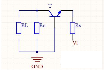
The common-base amplifier circuit has a small input resistance, a large output resistance, and good frequency characteristics. However, the common-base amplifier circuit has only voltage amplification capability and no current amplification capability. Let's look at the AC path circuit diagram directly.

The current flowing from the emitter into the collector is a common base amplifying circuit. Through the introduction of the common-emitter circuit, I believe that everyone should be familiar with the four components on the schematic.
In fact, the magnitude of this voltage amplification is the same as when the emitter of the common-emitter amplifier circuit is not connected, but the difference between the two is a negative sign. The meaning of each letter in the formula is the same as that of the common-emitter amplifier circuit. That is, β represents the amplification factor of the triode, R L′ is equal to R c and is RL, R b b′ is composed of the base lead resistance and the base body resistance, and the calculation method of R b′e is also the same as the common-emitter amplification circuit.
The common input amplifier has a large input resistance and a small output resistance, but only current amplification capability, no voltage amplification capability, and generally close to but less than one.
At first glance, the co-amplifier circuit with the sense that the emitter has no resistance is very similar. The difference is that the position of the AC ground is different. You can compare it to make it easier to distinguish.
It can also be seen from the formula that the voltage amplification factor is unlikely to be greater than 1, usually 1+β is large, and the latter is multiplied by a large resistance Re', so the result is close to 1. In this formula, a Re' is different from the formulas of the above two kinds of amplifying circuits, and its value is equal to Re and R L , and the other letters represent the same meaning as above.
These three basic configuration amplifier circuits are very important. Of course, these three formulas need to be written down. When analyzing complex circuits, the formula can be directly applied, which is convenient to calculate, not only the correct rate but also the speed.
If you want to know more, our website has product specifications for the triode amplifier, you can go to ALLICDATA ELECTRONICS LIMITED to get more information

