L298N DC motor drive chip.
DC motor driver chip selection
First, the most used is the H-bridge driver chip: L928N
The chip is simple, inexpensive, and easy to buy. It integrates two H-bridge circuits into one chip, with PWM control and current acquisition. But it has two serious drawbacks:
1) The loss on the H-bridge circuit is too large.
2) The manual requires the motor drive voltage to be 2.5V higher than the control logic voltage. Not suitable for single-powered cars.
Second, triode H bridge
Low-power bridge with 8550+8050: When driving at 5V, driving a small motor of about 100mA, the voltage drop across the bridge is less than 0.5V.
The bridge with D772+D882 has a larger current: at 7.2V, the voltage drop is less than 1V at 200-300mA.
Third, MOS tube bridge
MOS tube efficiency is definitely the highest. But there are two problems:
1) MOS tube is relatively fragile, so you need to pay great attention when using it. For example, when switching on, you should carefully study the timing, otherwise it will easily cause the bridge to pass through and burn the MOS tube;
2) The high-power MOS transistor gate requires a relatively high driving voltage, otherwise it cannot be normally turned on. Therefore, when driving with a battery, it is necessary to add a booster circuit.
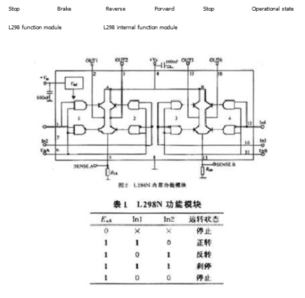
The L298 is a product of SGS. The more common one is the L298N in a 15-pin Multiwatt package. The internal also contains a 4-channel logic driver circuit. It is convenient to drive two DC motors or one two-phase stepper motor.
The L298N accepts the standard TTL logic level signal VSS, which can be connected to 4.5 to 7 V. The 4-pin VS is connected to the power supply voltage, and the VS voltage range VIH is +2.5 to 46 V. The output current is up to 2.5 A and can drive inductive loads. The emitters of the 1 and 15 pin tubes are separately led out to access the current sampling resistor to form a current sensing signal. L298 can drive 2 motors, OUT1, OUT2 and OUT3, OUT4 can be connected to the motor separately. We chose to drive one motor in this experimental device. The 5, 7, 10, 12 pins are connected to the input control level to control the forward and reverse rotation of the motor. EnA, EnB is connected to the control enabler to control the motor's stall. Table 1 is the L298N functional logic diagram.

The logic diagram of In3, In4 is the same as in Table 1. It can be seen from Table 1 that when EnA is low, the input level acts on the motor control. When EnA is high, the input level is high and low, and the motor is positive or negative. The same low-level motor stops, the same high-level motor brakes. The principle of the L298 controller is as follows:
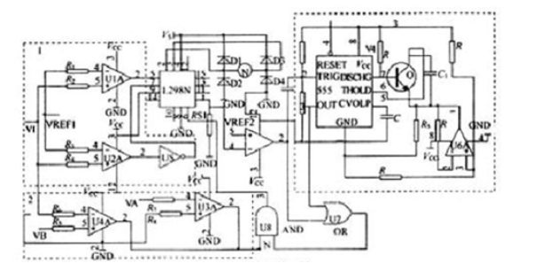
Figure 3 is a schematic diagram of the controller, consisting of three dashed block diagrams.

Fig.3
Below are the three dotted block diagram functions:
(1) Dotted block diagram 1 controls the motor to reverse direction, U1A, U2A is the comparator, VI is the voltage from the furnace pressure sensor. When VI>VRBF1, U1A outputs a high level, U2A outputs a high level through the inverter to a low level, and the motor rotates forward. When VI
(2) In the block diagram of the dotted line 2, the two comparators U3A and U4A form a double-limit comparator. When VB
(3) The broken line block diagram 3 is a long delay circuit. U5A is a comparator, Rs1 is the sampling resistor, and VRBF2 is the motor overcurrent voltage. The voltage on Rs1 is greater than VREF2, the motor is overcurrent, and U5A is output low. As can be seen from the above, block 1 controls the forward and reverse rotation of the motor, and block 2 controls the magnitude of the ripple of the furnace body. When the pressure of the furnace body is too small or too large, the motor is turned to the fixed position at both ends to stop, according to the steady state operation equation of the DC motor [3]
: U=CeФN+RaIa
Where: Ф is the magnetic flux per pole of the motor;
Ce is an electromotive force constant;
N is the number of motor revolutions;
Ia

