Methods for repairing LCD color TV with oscilloscope
l Determine the fault range based on the fault characteristics of the waveform
In a faulty LCD color TV, the waveform changes are very different, but there are still some rules to follow, and the analysis mainly includes the following situations:
(1) Waveform amplitude and frequency deviation are too large
The waveform amplitude deviation is too large, reflecting that the circuit is not working properly. For example, the coupling capacitor variation or the resistance of the feed branch resistor increases, which generally attenuates the amplitude of the waveform. The change in the operating point of the amplifier also causes the amplitude of the waveform to change.
The waveform frequency deviation is too large, in addition to the waveform frequency offset, it should also include pulse width aberration. Pay attention to observation and analysis during maintenance.
(2) no waveform
This situation reflects that the signal is not sent to the detection point, it may be that the circuit has an open circuit, the signal is interrupted, and there may be a short circuit between the point and the ground.
(3) There is a clutter in the waveform
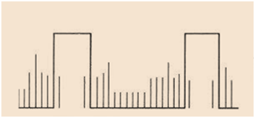
A clear waveform is not visible on the oscilloscope, but many lines are superimposed or displayed in a messy manner. One of the waveform lines is brighter and the others are darker, which is usually called the waveform "not clean", as shown in the following figure. The cause of this failure is the failure of the filter capacitor, leakage of some components or boards, and so on. Of course, if there is a power transformer near the oscilloscope working or the oscilloscope is poorly grounded, it will also cause such interference.

(4) Distortion of waveform shape
Causes of waveform distortion, common capacitors, resistance variable values, etc., and some are caused by the malfunction of the amplifier.
(5) An oscillating wave is superimposed on the waveform, indicating that there is parasitic damped oscillation in the circuit, which is more common in switching power supplies or high voltage circuit. The frequency of the parasitic oscillation is high, and it is easy to be radiated by the circuit, and then the circuit forms interference.
(6) Waveform reversal
The waveform reversal means that the test waveform is opposite in phase to the normal waveform, the forward pulse becomes a reverse pulse, or the reverse pulse becomes a positive pulse, and the oscillation wave is superimposed on the amplifier waveform to work abnormally or the gate circuit does not work. Caused normally.
l When using an oscilloscope to repair LCD TVs, there are several common methods.
1. Joint probe measurement
For dual-track oscilloscopes, there are usually two 10:1 attenuation probes. When measuring high-amplitude voltage waveforms such as reverse pulses, if there is no 100:1 probe, you can also connect these two 10:1 probes in series. And make up a 100:1 probe. When in use, both probe attenuation switches are set to ×10 position, which are connected end to end, which is very convenient to use.
2. Signal tracing
The signal tracing method is to measure the voltage waveform of certain key points or extended measurement points along the direction of the signal according to the fault phenomenon during the process of repairing the liquid crystal color TV. The operator only needs to master the circuit structure of the color TV, master the characteristics of the key signals and the normal waveforms. By testing the test points, the fault location can be quickly found. This is the most common method used in maintenance.
3. Monitoring measurement
For faults that occur irregularly, or that may occur during a long test, monitor measurement is used to attach the oscilloscope probe to the suspected measurement point for a longer period of time. If the lead or solder joint of the measured point is too small, it is not convenient to suspend the probe. You can add a thin hard wire with a solder length of no more than 1cm on the solder joint, but be careful not to short-circuit the other solder joints nearby. Lightly hang the oscilloscope probe on the wire, do not pull the copper foil on the board

