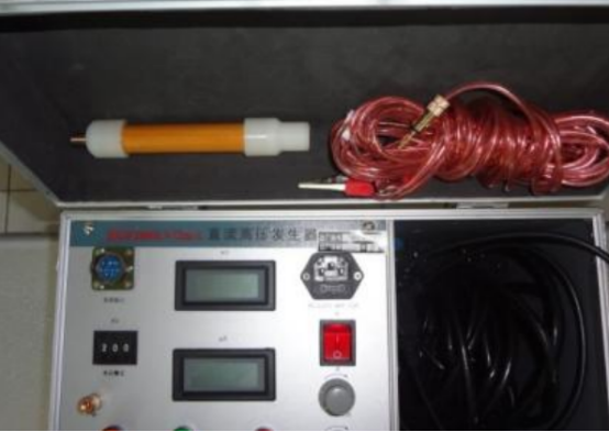
What are the common fault solutions for DC high voltage generators?
The high-voltage shielded ammeter is attached to the DC high-voltage generator as a digital micro-ampere meter. The jack on the top of the meter is the line jack for connecting to the test product, and it also serves as a power switch. Please unplug the plug when not in use and turn off the power automatically. When replacing the battery, please open the screw on the top cover. After replacing the battery, please buckle the cover and tighten with the screw. Open the back cover when changing the battery.

1. The DC high-voltage generator connects the ground terminal on the control box panel and the ground terminal of the high-voltage tower with a ground wire and connects it to the ground wire of the site or laboratory. To ensure the safety of you and the equipment, be sure to check the ground wire repeatedly to ensure that all parts are well grounded.
Connect the control box and the high-voltage tower with the provided seven-core cable. The two ends of the cable are the same fast aviation plug. Pay attention to insert the notch on the side of the plug to the rough convex part inside the socket and tighten it clockwise. (Use either end of the cable to connect to the control box or high-voltage tower) Connect the power cord, the power supply is a single AC 220v, power frequency 50hz.
2. Turn on the power switch. At this time, the power switch light (green) and the panel indicator are on. Then the high voltage indicator (green) lights up, if the high voltage indicates that the buzzer is in the on position, it will beep to remind the operator to increase the high voltage. At this time, rotate the high voltage output adjustment knob clockwise to increase the voltage and the voltmeter will display as The voltage kv value on the load test product, the ammeter shows the sum of the current flowing through the test product and all leakage currents, but does not include the current of the built-in high voltage divider. The current is measured in microampere units ua.
If the power switch is turned on, the high-voltage indicator (green) does not light, and the "zero" light (red) lights in the fault display, it means that the high-voltage output adjustment button is not at the zero position, please turn this button counterclockwise to "zero" Position, and return the fine-tuning voltage knob to the zero position, some "zero return" lights are off, and then adjust clockwise to increase the voltage.
3. If voltage regulation protection within the rated output voltage range is not needed, turn the overvoltage protection setting knob clockwise to the maximum value. At this time, when the output voltage exceeds the rated output voltage, it will automatically protect and cut off the high voltage. If voltage regulation protection is required within the rated output voltage range, please increase the no-load boost to the predetermined protection voltage according to the above steps, and then slowly turn the overvoltage protection setting knob counterclockwise to the required voltage. For over-voltage protection, the "over-voltage" indicator lights, keep the over-voltage protection setting knob set at this position, return the boost knob to the zero position, and turn off the power. Connect the test product, and then automatically cut off the high voltage when the boost voltage exceeds the predetermined voltage.
4. When over-voltage, over-current and other faults occur, the high voltage is automatically cut off, the high-pressure indicator (green) is off, the buzzer stops beeping, and the corresponding fault indicator lights up, indicating that the test product has been short-circuited. The high-voltage output adjustment knob returns to the zero position, the fine adjustment knob is also at the zero position, then turn off the power switch, and then turn on the power switch to remove the protection and boost again. When shutting down in normal operation, you should first return the high-voltage adjustment knob counterclockwise to the zero position, and then return the fine-tuning voltage knob to the zero position, and then turn off the power switch. The power switch is also used to protect the reset switch, so when the fault indicator (except the zero return indicator) is on, the power switch should be turned off and then on to release the protection and boost again.
5. When the load of the DC high-voltage generator is a large capacitive load, in order to avoid excessive charging current and trigger over-current protection, please slow down the boost speed appropriately. After the test is completed, turn the output voltage adjustment knob counterclockwise to the zero position. At this time, the voltmeter still displays the voltage value on the sample. Please wait for the sample to discharge through the high voltage tower to below 20kv before discharging with a ground rod to ensure Safety.
If you want to know more, our website has product specifications for generators, you can go to ALLICDATA ELECTRONICS LIMITED to get more information

