What is the working principle of the filter circuit?
The voltage outputted by the rectifier circuit is a one-way pulsating voltage and cannot be directly used in an electronic circuit. Therefore, the output voltage should be filtered to eliminate the AC component in the voltage and become DC power for use in the electronic circuit. In the filter circuit, devices that have special impedance characteristics to alternating current, such as capacitors and inductors, are mainly used.
Filtering principle
1. Characteristics of one-way pulsating DC voltage
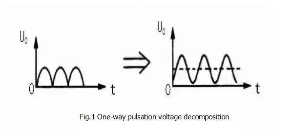
As shown in Figure 1 (a). It is a one-way pulsating DC voltage waveform. It can be seen from the figure that the directionality of the voltage is consistent at all times, but it is fluctuating in voltage amplitude, that is, the voltage exhibits change periodicity on the time axis, so it is pulsating.
However, according to the waveform decomposition principle, this voltage can decompose a DC voltage and a set of AC voltages with different frequencies, as shown in Figure 1(b). In Fig. 1(b), the dotted line portion is a unidirectional pulsating DC voltage U. DC component, in the solid line is the AC component in the UO.

2. Capacitor filtering principle
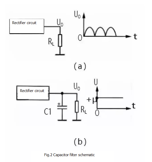
According to the above analysis, the unidirectional pulsating DC voltage can be decomposed into two parts, AC and DC. In the filter circuit of the power supply circuit, the characteristics of the "Isolated DC and conducted AC" of the capacitor and the energy storage characteristics, or the characteristics of the "straight traffic" of the inductor can be utilized to filter out the AC component in the voltage. Figure 2 shows the schematic of the capacitive filter.
Figure 2 (a) shows the output circuit of the rectifier circuit. After the AC voltage is passed through the rectifier circuit, a unidirectional pulsating direct current, that is, a UO in the circuit, is output.
Figure 2(b) shows the capacitor filter circuit. Since the capacitor C1 is equivalent to an open circuit to the direct current, the DC voltage output from the rectifier circuit cannot pass through C1 to ground, and only the load RL is shown as RL. For the AC component of the rectifier circuit output, because C1 has a large capacity and a small capacitive reactance, the AC component flows to the ground through C1 and cannot be added to the load RL. Thus, the required DC voltage +U is taken out from the unidirectional pulsating direct current by the filtering of the capacitor C1.
The larger the capacity of the filter capacitor C1, the smaller the capacitive reactance to the AC component, and the smaller the AC component remaining on the load RL, the better the filtering effect.

3. Inductive filtering principle
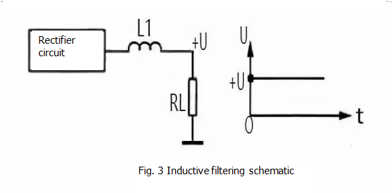
Figure 3 shows the schematic of the inductive filtering. Since the inductor L1 is equivalent to the path of the direct current, the direct current voltage output from the rectifier circuit is directly applied to the load RL.

For the AC component of the rectifier circuit output, because of the large inductance of L1, the inductance is large, which greatly hinders the AC component and prevents the AC from flowing through C1 to the load RL. Thus, the required DC voltage +U is taken out from the unidirectional pulsating direct current by the filtering of the inductor L1.
The larger the inductance of the filter inductor L1, the greater the inductive reactance to the AC component, and the smaller the AC component remaining on the load RL, the better the filtering effect, but the DC resistance will also increase.
If you want to know more, our website has product specifications for the filter, you can go to ALLICDATA ELECTRONICS LIMITED to get more information

