How does an infrared proximity sensor work?
Industry analysts predict that the market will grow at a compound annual growth rate of 27% by 2023, when TWS is expected to surpass all other types of wireless and wired headsets in sales.
Facing such rapid growth, earphone manufacturers will inevitably face fierce competition, and the choice of consumer products will be affected by important parameters such as audio quality, comfort and reliability.
Another crucial factor will be battery life to maintain longer battery life. One way to reduce power consumption is to make sure that the earbuds automatically stop playing when you remove them from your ears, and turn them on again when you insert them.
This requires short-range proximity sensing. In mobile phones, an infrared (IR) proximity sensing module detects when the phone is held on the user's face during a voice call, which can turn off the display. The following article describes how this technology can be adapted to small space TWS earbuds and how to reliably detect whether the earbuds are inside or outside the ear.
Working principle of infrared proximity detection
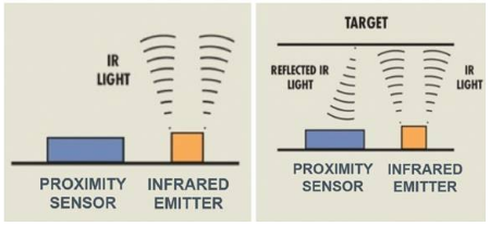
The basic operation of infrared proximity sensor is shown in Figure 1.

Figure 1: IR proximity sensor detects light reflected from nearby objects
It contains two main components:
An invisible infrared emission source that emits modulated light pulses. Ideally, the emitted power should be concentrated in a narrow band.
A photodiode (light sensor) with peak sensitivity at a wavelength that matches the peak intensity of the transmitter.
By strictly controlling the operating wavelength of the system and modulating the pulse, the sensor system can be protected from noise. The noise mainly includes interference from external infrared energy sources (such as sunlight) and internal reflection (crosstalk) from the module housing to the optical system. other parts. When the emitted infrared light hits the target in the range, it will be reflected on the photodiode. The photodiode converts the measured infrared energy into a digital value, which will increase proportionally as the target approaches.
In TWS earbuds, the proximity sensor is usually configured to trigger a detection signal when the object (in this case, the user's ear is open) is within 3 mm, and release the signal when the nearest object is within a distance of 10 mm . Reliable proximity detection requires sufficient signal-to-noise ratio (SNR). To determine the SNR, the manufacturer needs to calculate the difference between the detection threshold and the release threshold count divided by the baseline jitter value (when there are no objects in the range):
(Average detection count value) – (Average release count value)
(Jitter count value)
Generally, when this ratio is> 4, the SNR is considered acceptable.
Why every mW is important
Proximity sensors can reduce power consumption by detecting when the earbuds are removed from the ear and entering standby mode, but the sensor itself consumes energy: most of the sensor's energy consumption is attributed to the infrared transmitter. Fortunately, earplug designers can use one of two techniques to limit the power consumption of the sensor. The first is by controlling the launch cycle. In ams' integrated proximity sensor module TMD2635, the duty cycle configuration is easy to control (see Figure 2).

Figure 2: Pulse timing of a single proximity event in the TMD2635
The number of times the emitter is pulsed (PPULSE) and the duration of the effective drive current (PPULSE_LEN) of each pulse can be adjusted. The power consumption is proportional to the number of pulses and the pulse length. You can increase or decrease the total time of a PRATE, which is the main method for controlling the duty cycle. System designers can also introduce latency (PWTIME) between proximity measurement cycles.
The second way to control the duty cycle is through a signal generated at the application software level. Here, the host processor can be programmed to cycle the active / inactive state of the sensor in a polling or interrupt-driven manner. The polling method enables the host MCU to precisely control the system timing. Here, the proximity sensor is usually in a static low power state.
The host microcontroller periodically issues commands to wake up, take a proximity measurement, and then return to a static state. In this polling mode, the designer can configure an optimal duty cycle that uses minimal power while providing an acceptable wait time, i.e. the delay between the user inserting / removing the earbud and the sensor detection event .
In the interrupt-driven method, the MCU wakes up the sensor, reads its previous sample, and then makes it free-running. When the next data event occurs, the sensor sends an interrupt signal to the host, and then automatically goes to sleep. The advantage of this interrupt-driven approach is that the designer can choose which type of event will generate an interrupt signal. This allows the system to offload many tasks from host firmware to sensors. Since the CPU in the host consumes power, offloading can save power. Therefore, when the TMD2635 performs its "sleep after interrupt" function, it will automatically disable its internal oscillator and enter a low power state.
The TMD2635's programmable threshold feature is particularly useful for triggering an interrupt when an adjacent data event falls outside a preset range between the high count threshold and the low count threshold, which can be set to only after the count has repeatedly exceeded the threshold window multiple times Triggering, this function and other interrupt filtering functions are implemented in the hardware of the TMD2635, thereby reducing the burden on the host processor.
It is worth noting that compared to polling, the timing in interrupt-driven mode is less deterministic, and the event-driven duty cycle will change with the response time of the host processor and the number of neighboring events. Unless a simplified preset is made, this variability makes accurate power calculations difficult, and benchmarking is often the best way to determine power consumption under dynamic operating conditions.
In interrupt-driven mode, the sensor spends most of its time in free-running idle mode, which typically consumes an average current of 30 µA, which consumes more power than polling, which typically consumes 0.7 µA only when the sensor is in sleep mode Of current.
In the module-based transmitter TMD2635 proximity detection system, a low-power vertical cavity surface emitting laser (VCSEL) can bring further advantages. Most infrared proximity sensors have an LED emitter, but VCSELs can provide higher electro-optic conversion efficiencies, typically ten times higher than LEDs. In addition, because the beam is very narrow and the angle of view is only 1 ° to 5 °, the light energy of all transmitters can be aimed at the target. As a result, compared to equivalent LED-based sensor systems, the total power consumption is significantly reduced, crosstalk interference is reduced, and SNR is higher.
Save space
Compared with earlier devices, the latest IR proximity sensor module integrates VCSEL technology, which has a substantial improvement in power consumption. Sensor manufacturers are also adjusting their product designs to fit the tight space inside TWS earbuds while maintaining a high level of optical performance.
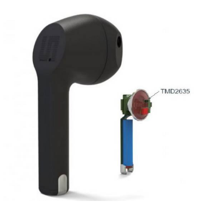
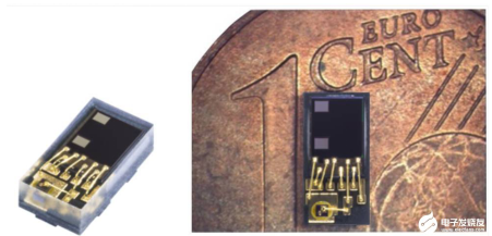
Figure 3 shows that the proximity sensor can take up very little space in the TWS earphone reference design developed by ams. The TMD2635 used in this design has a package size of 1mm x 2mm x 0.5mm (see Figure 4).

Figure 3: TWS Headphone Reference Design Based on TMD2635 Module

Figure 4: TMD2635 proximity detection module is very small, occupying only 1mm3
The biggest difficulty in making such a small device is the optical design: ensuring that the emitted and reflected beams have clear paths to and from the target, while limiting the effect of crosstalk on photodiode measurements. In TMD2635, ams achieves this by combining component miniaturization, precise assembly, and high-performance optical stacking (see Figure 5).

Figure 5: Side view of TMD2635
The holes above the plutonium emitter and photodiode are covered by a polycarbonate material that is highly transparent to infrared light. The via can be round (1.5 mm in diameter) or oval (1 mm x 2 mm), giving designers greater flexibility when placing the sensor in the earbud housing.
In conclusion
The TMD2635 module combines configurable power management technology, efficient VCSEL transmitters and optical components, and now provides a way for designers to more easily integrate proximity sensing in a small space inside the earbuds while providing Reliable detection of headphone position. This module's laser transmitter's high optical efficiency and low sleep mode current help keep average power consumption at a very low level, helping earbuds manufacturers to extend their product life, even with batteries as small as 25 mAh.
If you want to know more, our website has product specifications for the infrared proximity sensor, you can go to ALLICDATA ELECTRONICS LIMITED to get more information

