How the nVIDIA MCP78 chipset motherboard works?
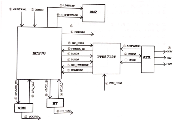
The nVIDIA MCP78 chipset motherboard works as shown in figure 1.

Figure 1 Schematic diagram of the nVIDIA MCP78 chipset motherboard.
The working process of the nVIDIA MCP78 chipset motherboard is as follows.
1. The power supply outputs the 5VSB voltage to the 1O chip and the 5VSB step down to + 3.3VDUAL to supply the MCP78 Bridge with the hold-on power.
2. 25MHz reported vibration to provide MCP78 with 25MHz reference frequency.
3. The 10-O chip sends a RSMRST# signal to the MCP78 to indicate standby voltage is good.
4. Short switch generates PWR_BTN# trigger signal to 1O chip ITE8712F.
5. The 10O chip converts the SIO_PWRBTN# signal to the MCP78 request to power up.
6. The MCP78 generates high levels of SUSC# and SUSB# to the 1O chip to indicate that power is allowed, while the SUSC# is powered on memory.
7. The SUSB# signal enters the 1O chip and converts the PSON# continuously low to the ATX green line.
8. Low green cable, + 3.3 V, + 5 V, + 12 V main power supply. Through the circuit step down to get the bridge power supply.
9. After the power supply is stabilized, the power output ATXPWRGD high level to the IO chip indicates that the power supply voltage is normal.
10. The IO chip converts the PWROK_SB signal to the MCP78 to indicate that the power supply voltage is normal.
11. MCP78 sends a CPUVDD_EN signal to the VRM power management chip.
12. The power management chip works and the control circuit generates the CPU-powered VCORE.
13. After the VCORE voltage stabilizes, the power management chip outputs the CPU_VLD signal to the MCP78 to indicate that the CPU power supply is normal.
14. MCP78 sends out HTVDD_EN signal to HT bus power supply control circuit.
15. The HT bus power supply circuit works in step-down and is powered by the HT_1.2V bus.
16. The HT_1.2V bus power supply voltage is converted into a HT_VLD signal to the MCP78 indicating that the bus power supply is normal.
17. MCP78 sends an H_CPUPWRGD signal to the CPU, to indicate that the motherboard is powered properly.
18. MCP78 sends out a SIO RST# signal to reset the IO chip.
19. MCP78 sends a PCIRST# signal to reset the PCI slot.
20. MCP78 sends a LDTRST# signal reset CPU, CPU to start working.
This article is from Allicdata Electronics Limited. Reprinted need to indicate the source.

