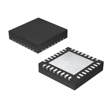
Measurement and control FPGA
An FPGA is a chip with reconfigurable logic gates. Unlike a vendor-supplied ASIC chip, the FPGA can be configured and reconfigured for each application's different needs. Because FPGAs allow custom algorithms to be implemented in hardware, they have the advantages of precise timing and synchronization, fast decision making, and simultaneous execution of parallel tasks. On a PC or a platform with an RTOS and a microprocessor, the processor must time-multiplex multiple tasks, while the FPGA can be configured as multiple independent parallel computing resources, in short, as much on the chip. Like a microprocessor, these microprocessors are optimized for specific tasks.
The flexibility and performance of FPGAs make them a very efficient technique for processing input and output. If you want to calculate analog or digital events that are more interesting than the simple rising or falling edges of the counter processing, or to confirm an input mode based on a specific sequence of events or a custom communication protocol, then trigger an analog operation after a few nanoseconds. The FPGA can be used to monitor the input signal to quickly determine and react. In addition, a system can be created to read the pulse width modulated signal and quickly calculate the duty cycle. Further, the FPGA can be configured to communicate using a custom digital protocol, such as decoding the input information and then encoding the information as an output. The data packet is sent out again. This fast decoding helps to read and interpret the position and velocity information when connected to a non-standard encoder. You may even want to do all of the above at the same time and synchronize these operations with each other and with other input and output tasks.
So what is the output situation? Communicating and generating PWM signals through custom digital protocols is a good example of this type, and it is also possible to simulate an electronic device or sensor connected to a physical system. If you do this with a software-based system, even with an RTOS, the performance of the output may not be enough. For the main control algorithm, it may only need to run at a few kilohertz frequency, which will cause the CPU resources to be idle, and it just tells the output what to do and when to do it, and does not specify what to do. Specifically, assume that your embedded system is an engine simulator used by customers to test engine control modules, model the car engine and perform real-time simulations based on the model, through analog and digital I/O and controllers. Communication. If the model is operated as directed by the controller in a particular test, the engine starts to run, but it is very difficult to adjust the cylinder pressure sensor analog output in real time to make the controller believe that it is connected to a real running engine. It must be formed during operation to respond to commands from the controller. However, if you are using an FPGA, you can configure it to generate an advanced output signal based on the simulation model.


