Sound card chip and interface circuit analysis and fault maintenance.
1. Introduction of sound card chip.
The sound card chip is used to restore sound and process microphone signal input. There are many capacitors near the sound card chip in the motherboard, which are used for audio signal coupling. The ALC662 and ALC655 sound card chips are shown in figure 1.

(a) AL662 (b) ALC655.
Fig. 1 Sound card chip.
2. The working principle of sound card chip circuit.
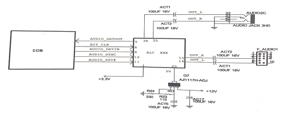
The sound card chip circuit is shown in figure 2. The sound card chip is connected to the North Bridge chip through the audio bus of 5, 6, 8, 10, 11 pins. The sound card chip first needs to get one pin 3.3V and 25 pins 5V power supply. The south bridge chip sends the clock signal BIT_CLK and reset signal AUDIO_RST# to the sound card chip through the bus, and the south bridge chip recognizes the sound card chip through AUDIO_SDAIN and AUDIO_ SDOUT data lines. When the sound needs to be restored, the North Bridge chip transmits the audio signal to the sound card chip through AUDIO_SDAIN, and after being processed by the sound card chip, the output audio signal from 14 pins and 15 pins is sent to the front panel audio interface through capacitance coupling. The audio signal is output from 35 pins 36 pins and sent to the rear audio interface through capacitance coupling.

Fig. 2 Sound card chip circuit.
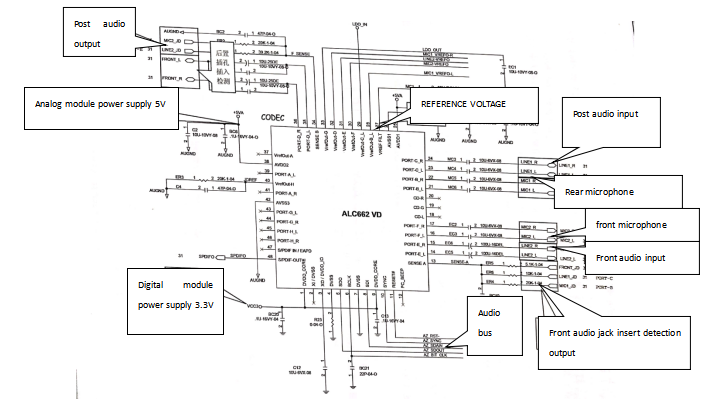
The application circuit of ALC662VD sound card chip is shown in figure 3, which indicates the important pin position.

Fig.3 The application circuit of sound card chip.
3. Troubleshooting method of sound card chip.
(1) The sound card chip is not recognized.
1. Check the 1 pin 3.3 V of the sound card chip and the 5 V voltage of 25 pin is normal. The short circuit of the sound card chip 25 pin will cause the output voltage of the 78L05 to be pulled down.
2. Check that the 2-pin clock signal of the sound card chip is about 1.5 V (the HD sound card chip does not need the bus clock signal).
3. Remove the sound card chip and check it for 5, 6.8, 10 pin. The ground value of the 11 pin pad should be similar, if the short circuit indicates that the south bridge chip is damaged, the infinity indicates that the south bridge chip is broken.
4. The above conditions are normal, first replace the sound card chip, and finally replace the south bridge chip.
(2) abnormal sound.
1. Check the peripheral capacitance for 2.5V voltage.
2. If the 2.5 V voltage is normal, replace the sound card chip.
(3) No sound or mono.
1. Check the sound card chip 35, 36 pin voltage is 2.5 V. No 2.5 V first change the sound card chip, and then replace the 27-pin connected REF capacitor.
2. If the 3536 pin voltage of the sound card chip is 2.5V, but there is no sound or mono, from the corresponding pin of the sound card chip to the audio interface, check that there is something wrong with the line (the non-HD sound card chip should pay attention to the front audio jumper cap).
3. The above conditions are normal, and finally replace the audio interface.
(4) abnormal input or abnormal MIC.
Check that the corresponding pin position 2.5V is normal, can refer to no sound or mono maintenance. HD sound card chip to detect the problem, check the SENSEA or SENSEB circuit.
If you want to know more, our website has product specifications for Sound card chip and interface circuit, you can go to ALLICDATA ELECTRONICS LIMITED to get more information

