What are the RF microwave power amplifiers?
Amplifiers have different classification methods. It is customary to classify the amount of time that an amplifier component operates in a complete signal swing period, that is, the difference in conduction angle. By arranging different bias conditions for the amplifier components, the amplifier can be made. Work in different states. In the EMC field, the most commonly used biasing methods in solid state amplifiers are Class A, Class AB and Class C.
Class A amplifier
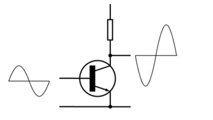
The active devices of Class A amplifiers are turned on during the entire period of the input sinusoidal signal. It is generally accepted that Class A and linear amplifiers are synonymous, and the output signal is a linear amplification of the input signal. In wireless communication applications, consideration must be given to The situation when complex modulation signals. In EMC applications, the input signal is relatively simple and the amplifier must operate at the power compression threshold. Class A amplifiers are commonly used power amplifiers in the EMC field, and their working schematics are shown in the figure.

Class A amplifier working principle diagram
Regardless of the presence of an RF input signal, the bias setting of the Class A amplifier is such that the quiescent operating point of the transistor is centered at the device current to ensure that it operates in a linear operating region with sufficient voltage range to follow the entire input. Changes in signal amplitude are replicated without being clipped or compressed.
Advantages of Class A amplifiers:
Class A design is simpler than other types of designs, and the output section can have one device.
When the device operates in a linear portion of its transmission characteristics through the bias setting, the amplifier can reproduce the input signal with more power with more precision, and the output power is also increased by 1 dB when the input signal power is increased by 1 dB, so it is a linear amplifier.
When operating in the linear region, the energy produced by other frequency components is small, that is, the harmonics are small.
Because the device is always active through the bias voltage setting and will not be turned off, there is no "on" time.
Continuous wave and pulsed continuous wave signals can be faithfully reproduced.
Disadvantages of Class A amplifiers:
Because the quiescent operating current is about half of the maximum output current, the efficiency is relatively low. In theory, the maximum efficiency is 50%, but the actual efficiency will be reduced by the loss of the output, such as filters, combiners, couplers, isolators, power conversion efficiency, etc., which may reduce the actual efficiency by about 10%.
If higher output power is required through Class A amplifiers, the wasted power and accompanying heat generation will increase significantly. The amplifier can consume up to 9 watts of heat for each watt of power delivered to the load. For high-power Class A amplifiers, this means having very large and expensive power supplies and heat sinks.
For Class A power amplifiers with insufficient heat dissipation, a 10°C increase in temperature will result in a significant reduction in the MTBF of internal power devices.
Class AB amplifier
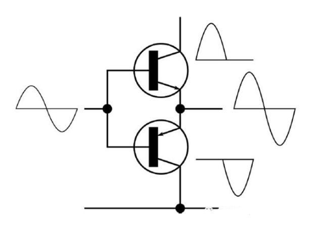
Before discussing class AB amplifiers, let's briefly talk about class B amplifiers. The transistor bias of the Class B amplifier allows the device to conduct only for half a cycle of the input signal and to turn off during the other half of the cycle. To reproduce the signal for the entire cycle, a dual-tube Class B push-pull circuit can be used, as shown. Class B amplifier offset settings
This makes the device's output current zero when there is no input signal, and each device operates only during a specific signal half cycle. Therefore, the class B amplifier has high efficiency and can theoretically reach 78.5%. However, the crossover distortion caused by the alternate opening and closing of the two tubes makes the linearity poor. The presence of this crossover distortion makes it unsuitable for commercial electromagnetic compatibility standards. Class AB amplifiers are also commonly used in the EMC field, and their working schematics are shown in the figure.

Figure: Working principle diagram of class AB amplifier
Class AB amplifiers attempt to make the operating efficiency close to that of Class B amplifiers, while linearity is close to that of Class A amplifiers. By adjusting the bias voltage setting, each tube in the Class AB amplifier can be turned on in the half cycle of the input signal like a Class B amplifier, but in the two half cycles each tube will have A small area that is turned on avoids the interval where the two tubes are simultaneously closed. As a result, when the waveforms from the two devices are combined, the crossover distortion caused by the intersection is greatly reduced or completely eliminated. By precisely setting the static operating point, the Class AB amplifier can ensure that its harmonic/distortion performance is sufficient to meet the requirements of the EMC field, that is, its linearity can meet the commercial electromagnetic compatibility test standards IEC61000-4-3 and IEC61000-4- 6 needs.
Class AB amplifiers sacrifice a bit of efficiency compared to Class B amplifiers for linearity, but have higher efficiency (60% to 65% theoretically) compared to Class A amplifiers.
Advantages of Class AB amplifiers:
The frequency range is smaller and the price is cheaper.
Power efficiency is greatly improved compared to Class A amplifiers.
Class AB amplifiers can be designed to use fewer devices than Class A, for the same power class and
Air-cooled, lighter than the cooler of a Class A amplifier.
Disadvantages of class AB amplifiers:
The generated harmonics need to pay attention to the specifications given by the specific products, especially the second harmonic. Class AB amplifiers can significantly suppress the harmonics by carefully adjusting the bias settings and using the push-pull topology.

