What is solid state RF power amplifier technology?
As the broadcast enters the digital development model, the RF power amplifiers in the all-solid-state PDM and DAM medium-wave broadcast transmitters that are produced and operated, that is, the final stage of the power amplifier, all use FET tube-type D-type amplifiers.
The high-frequency power amplifier is essentially a controlled source energy converter that converts the DC energy supplied by the power source into high-frequency AC energy under the excitation of the high-frequency oscillating voltage. Because the field effect tube has excellent performance in low noise, high power and high efficiency, it is the most ideal amplifying device for power amplifier.
It is characterized by high input impedance, large output power, fast switching speed and bandwidth, high frequency characteristics. The modulated power amplifier is where the high voltage and large currents in the all-solid medium wave broadcast transmitter converge, and it is an absolute high fault area. Generally, the modulation and power amplifiers on the medium and small power machines are separated, and the medium and large power machines are combined into one. More common in 50 kW, 100 kW, 150 kW machines.
Circuit structure and principle
RF power amplifiers are different from other tube RF power amplifiers that work in Class A, Class B, and Class C. They do not require high voltage. Unlike other low frequency power amplifiers, there is not much bandwidth. The field effect transistor of the D-type amplifier works in the switching state, and the drain dissipation power is very low. Although the on-off and off-period work is very powerful in the linear region, the operating frequency is high, the transition period is very short, and the working efficiency is higher than that of the conventional power amplifier. Greatly improved, in fact, it can be more than 90%.
The bridge power amplifier is the RF power amplifier in the medium wave broadcast transmitter that is now produced and operated. The bridge power amplifier is connected by four FETs in the form of bridges. The connection method of working in the D-type switch amplification mode is called bridge type. Power amplifier, this full bridge connection is an H-type, so it is also known as H-type D-type amplifier. The full-bridge circuit is composed of two half-bridges. The output of the left and right parts is connected to the opposite ends of the composite transformer primary coil. This structure is similar to the traditional push-pull circuit. The two RF power amplifiers are designed to be powered by separate power systems. The push signals are also independently input by the two bridges. The half-bridge operation of the RF power amplifier is utilized in the pre-driver stage.
The FET D-type amplifiers are composed of two or more pairs of tubes, which are divided into two groups of turns to conduct power amplification tasks. The excitation voltage that controls the FET to operate in the switching state may be a sine wave or a square wave. There are two kinds of actual circuits, namely current switch type and voltage switch type. Because the current is a square wave in the current switching circuit, the switching time of the FET switch cannot be ignored when the operating frequency is high, so the voltage switching circuit is used in the medium wave broadcast transmitter. It is divided into two modes: full bridge and half bridge.
Solid state RF power amplifier technology
1. RF microwave power amplifier and its application
An amplifier is a component used to reproduce a signal with greater power, greater current, and greater voltage. Amplifiers that are indispensable in signal processing can be either microchips in hearing aids or as large as multi-layer buildings to transmit radio signals to underwater submarines or outer space.
A power amplifier can be thought of as a circuit that converts a direct current (DC) input into radio frequency and microwave energy.
Not only does it require sufficient power to generate sufficient power at the RF and microwave frequencies in the field of electromagnetic compatibility, but also in areas such as wireless communications, radar and radar interference, medical power transmitters and high-energy imaging systems, each of which has its own frequency, Unique requirements for bandwidth, load, power, efficiency and cost.
RF and microwave power can be generated using different technologies and different devices.
2. Overview of RF Microwave Power Transistors
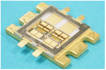
As semiconductor technology continues to advance, more and more devices and types are available for RF power amplifiers. Various packaged devices are commonly used, and Figure 1 shows a typical transistor with a cover removed. This is a balanced microwave transistor with a maximum power of 60W using a GaAs FET, suitable for push-pull class AB amplifiers.

Figure 1: Internal structure of a 60W GaAs FET
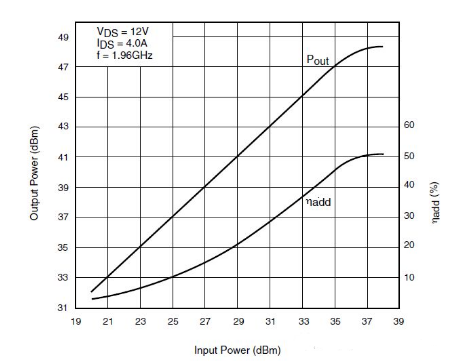
This transistor amplifier provides excellent linearity as emphasized by the basic standards in the EMC field, IEC61000-4-3 and IEC61000-4-6, as shown in Figure 2.

Figure 2: Input and output linearity of a transistor
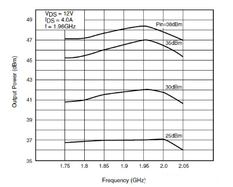
This transistor can provide the required power over the operating frequency range. Its output power versus frequency is shown in Figure 3.

Figure 3: Output power versus frequency for a transistor
If you want to know more, our website has product specifications for amplifier, you can go to ALLICDATA ELECTRONICS LIMITED to get more information

